


ال ESTUN E315P Timing Diagram shows how the CNC controller coordinates machine signals, beam movement, axis positioning, and hydraulic valve outputs during a complete مكابح الضغط bending cycle. It provides technicians with a clear reference for understanding what should happen at each stage of machine operation.
A complete bending cycle includes Fast Closing, Pressing, Dwell Time, Decompression, and Opening. By reading the ESTUN E315P Timing Diagram, operators and technicians can understand the relationship between these bending stages and the corresponding control signals, making it easier to analyze machine operation and troubleshoot abnormal sequences.
What Does the ESTUN E315P Timing Diagram Show?
ال ESTUN E315P Timing Diagram represents the sequence of commands and machine actions during a complete bending operation.
The beam process is divided into the following stages:
- No Command
- Fast Closing
- الضغط
- وقت البقاء
- إزالة الضغط
- افتتاح
- Return to No Command
During these stages, the controller coordinates the Start command, pedal input, UDP and LDP signals, programmed axis positions, and hydraulic valve outputs.
The diagram therefore provides more than a simple representation of beam movement. It shows how CNC commands, position signals, axes, and hydraulic actions work together throughout the bending cycle.
Image summary: The ESTUN E315P timing sequence shows beam status, control signals, axis positions, and hydraulic valve outputs during a complete bending cycle.
Understanding the Main Bending Cycle
The ESTUN E315P Timing Diagram divides the bending process into several consecutive stages. Understanding each stage makes it easier to determine where an abnormal machine sequence occurs.
Fast Closing
خلال Fast Closing, the beam moves rapidly downward toward the workpiece.
This movement reduces non-working travel time and improves production efficiency. The fast-closing stage continues until the beam approaches the transition point for the actual bending operation.
The control system then changes the corresponding signals and hydraulic outputs to enter the pressing stage.
الضغط
After fast closing, the machine enters الضغط.
The beam continues downward at the required working speed and performs the actual sheet metal bending operation.
At this stage, the hydraulic system generates the force required to form the workpiece. The transition from fast closing to pressing allows the machine to change from rapid approach movement to controlled bending movement.
وقت البقاء
Once the programmed bending position is reached, the controller can enter وقت البقاء.
During this stage, the beam remains at the required bending position for the programmed period.
The corresponding valve output remains controlled according to the bending sequence until the dwell stage is completed.
إزالة الضغط
After dwell, the machine enters إزالة الضغط.
During this stage, the hydraulic system transitions away from the pressing condition before the beam begins its return movement.
ال ESTUN E315P Timing Diagram shows decompression as a separate stage between dwell and opening, making it easier to understand the hydraulic sequence.
افتتاح
After decompression, the beam begins the افتتاح stage and moves upward.
The opening movement continues according to the programmed return conditions. Once the required upper position is reached, the bending cycle returns to the No Command condition and waits for the next operation.
What Signals Are Shown in Sequence Diagram A?
Sequence Diagram A provides a detailed view of the control signals involved in the bending process.
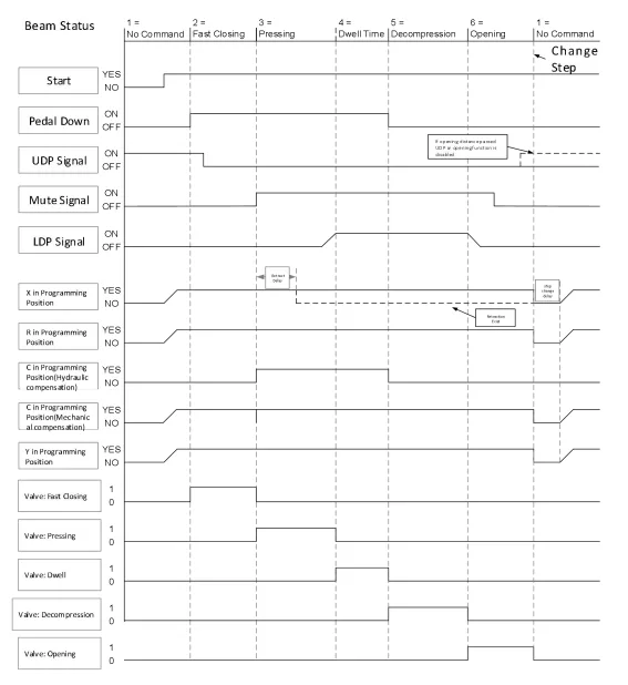
By comparing these signals on the ESTUN E315P Timing Diagram, technicians can see when individual commands become active or inactive during different stages.
Start and Pedal Signals
ال يبدأ و Pedal Down signals are involved in initiating and maintaining the required machine operation.
Their states change according to the active stage and operating conditions of the bending cycle.
When troubleshooting, these signals can help determine whether the controller has received the required operating command.
UDP and LDP Signals
The diagram also includes بروتوكول بيانات المستخدم (UDP) و LDP signals.
These signals are related to beam position and the transition between different movement stages. Their status helps the controller coordinate changes between fast closing, pressing, and opening.
Axis Programming Positions
The sequence diagram shows the programmed positions of several controlled axes, including:
- المحور السيني
- المحور R
- C-axis
- المحور Y
These axes do not necessarily move simultaneously. Their positioning status depends on the active bending step and machine configuration.
For example, the backgauge must reach the required programmed position before the corresponding bending operation can proceed.
How Do Hydraulic Valves Follow the Timing Diagram?
ال ESTUN E315P Timing Diagram also illustrates how hydraulic valve outputs correspond to different beam movements.
The main valve stages include:
- Valve Fast Closing
- Valve Pressing
- Valve Dwell
- Valve Decompression
- Valve Opening
During rapid downward movement, the corresponding fast-closing output is active. When the machine enters the actual bending stage, the pressing output takes over.
After the programmed bending position is reached, the system proceeds through dwell, decompression, and opening according to the required sequence.
This relationship allows the E315P to coordinate CNC commands with the hydraulic system throughout the complete bending cycle.
Image summary: Hydraulic valve outputs change sequentially during fast closing, pressing, dwell, decompression, and opening.
How Does X-Axis Retraction Work?
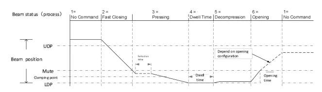
Sequence Diagram B focuses more closely on beam movement and X-axis retraction.
The ESTUN E315P Timing Diagram shows when the backgauge can retract relative to the beam movement. Retraction may be required to prevent the sheet from interfering with the backgauge during bending.
Retraction Delay Activation
According to the timing logic, the retraction delay is effective only when Waiting for Retraction is enabled.
When the speed-change signal becomes active, the controller starts the delay timer.
After the programmed delay expires, the X-axis moves to the required retraction position. The backgauge can then be repositioned for the next bending step according to the program.
Why Is Retraction Timing Important?
Correct retraction timing helps prevent interference between the backgauge and workpiece during bending.
If the X-axis retracts at an inappropriate time, it may affect workpiece positioning or the bending sequence.
The retraction movement must therefore be coordinated with beam movement and the programmed bending process.
How Is Opening Time Determined?
The ESTUN E315P Timing Diagram also shows the relationship between the speed-change signal and opening time.
According to the sequence information, Opening Time starts when the Speed Change Signal transitions from ON to OFF.
The UDP signal is also related to the upper beam movement. When the beam reaches the corresponding opening condition, the controller manages the transition according to the programmed sequence.
Understanding this relationship can help technicians check whether the beam opening process is occurring at the expected time.
Why Is the ESTUN E315P Timing Diagram Useful?
The ESTUN E315P Timing Diagram provides a visual reference for understanding how different parts of the press brake operate together during one bending cycle.
Technicians can use it to compare:
- Beam movement
- Start and pedal commands
- UDP and LDP signals
- Axis positioning
- Hydraulic valve outputs
- X-axis retraction
- Opening timing
This information is especially useful when the machine stops or behaves abnormally at a specific stage.
For example, if the beam completes pressing but does not begin opening, technicians can use the ESTUN E315P Timing Diagram to identify which signals and valve outputs should change during Dwell, Decompression, and Opening.
Instead of checking components randomly, the timing sequence provides a logical reference for determining which stage of the bending cycle should be inspected first.
الأسئلة الشائعة
What Are UDP and LDP Signals?
UDP and LDP are position-related signals used during beam movement. They help the controller coordinate transitions between different stages such as fast closing, pressing, and opening.
Their status can be checked together with other signals when analyzing an abnormal bending sequence.
Why Is There a Decompression Stage?
Decompression provides a transition between the pressing or dwell condition and beam opening.
Instead of moving directly from pressing to opening, the hydraulic system first enters the decompression stage according to the programmed control sequence.
Can the Timing Diagram Help With Troubleshooting?
Yes. The ESTUN E315P Timing Diagram can be used as a reference when the machine stops or behaves abnormally during a specific stage.
Technicians can compare the actual beam movement, input signals, axis status, and valve outputs with the expected sequence to determine which part of the process requires further inspection.
خاتمة
The ESTUN E315P Timing Diagram provides a clear overview of how the controller coordinates beam movement, axis positioning, control signals, and hydraulic valve outputs during a complete bending cycle.
By understanding the sequence from Fast Closing and Pressing to Dwell, Decompression, and Opening, technicians can better understand the operating logic of the E315P. The diagram also clarifies important functions such as X-axis retraction and opening-time control.
When an abnormal sequence occurs, using the ESTUN E315P Timing Diagram as a reference can help technicians identify the affected stage and perform more targeted troubleshooting instead of checking machine components without a clear sequence.


