


Regular ESTUN E315P Maintenance Checks are essential for maintaining reliable controller operation and preventing electrical or mechanical problems during press brake operation. Proper maintenance involves inspecting the controller installation, electrical connections, environmental conditions, power supply, and related components.
According to the ESTUN E315P maintenance recommendations, inspections are divided into daily checks and periodic inspections. Daily checks focus on installation security, wiring connections, terminals, and display conditions. Periodic inspections cover additional electrical and environmental requirements.
This guide explains how to perform ESTUN E315P Maintenance Checks systematically, including important safety precautions, inspection procedures, and corrective actions.
What Are ESTUN E315P Maintenance Checks?
ESTUN E315P صيانة Checks are routine inspection procedures designed to verify that the CNC controller and its associated electrical components remain in suitable operating condition.
The maintenance recommendations identify three main areas:
- Maintenance precautions
- Daily checks
- Periodic inspections
Daily checks focus on components that should be inspected regularly, while periodic inspections provide a more comprehensive evaluation of the controller’s installation and operating environment.
The recommended periodic inspection interval is every 6–12 months. Additional inspections are required when the device is relocated, its structure is modified, or the wiring system is changed.
Following these requirements helps technicians identify potential problems before they affect normal machine operation.
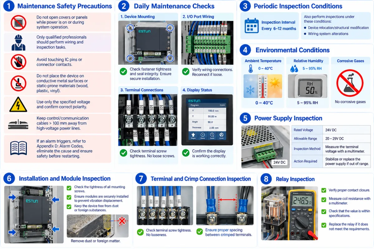
Step 1: Follow Maintenance Safety Precautions
Before beginning ESTUN E315P Maintenance Checks, technicians must follow the electrical safety precautions specified in the manual.
Do not open controller covers or panels while the power is on or while the system is operating. Wiring and inspection work should only be performed by qualified professionals.
Avoid touching integrated circuit pins or connector contacts directly, as improper handling may damage electronic components.
The controller should not be placed on conductive metal surfaces or materials prone to generating static electricity, such as wood, plastic, or vinyl.
Additional precautions include:
- Verify programs and parameters before operation.
- Use only the specified supply voltage.
- Confirm correct power supply polarity.
- Keep control and communication cables more than 100 mm away from high-voltage power cables.
Incorrect terminal wiring or reversed polarity may damage the controller’s electrical circuits.
If an alarm occurs, refer to Appendix D – Alarm Codes, identify and eliminate the fault, and confirm that the machine is safe before restarting.
Step 2: Perform Daily Installation Checks
The first daily inspection item is the controller’s physical installation.
Check whether the mounting fasteners are secure and whether the installed components remain properly positioned.
Also inspect the integrity of the relevant seals.
The standard requirement is that the device must be securely installed.
If mounting screws or fasteners are loose, tighten them appropriately before continuing with normal operation.
A secure installation helps prevent unwanted movement and maintains the intended mechanical mounting condition.
Step 3: Inspect I/O Wiring and Terminal Connections
Electrical connections are another important part of daily ESTUN E315P Maintenance Checks.
Start by inspecting the I/O port wiring.
Confirm that the connections are secure and that no wires have become loose.
If a connection is loose, reconnect it correctly according to the machine’s electrical wiring requirements.
Next, inspect the terminal connections.
The maintenance checklist requires technicians to check terminal screw tightness and confirm that no screws are loose.
If loose terminal screws are found, tighten them appropriately with the power safely isolated.
These checks help maintain reliable electrical connections between the controller and the machine’s associated components.
Step 4: Check the Controller Display Status
The daily inspection checklist also includes the controller display.
Verify that the display presents information correctly and that the visible status corresponds with the expected operating condition.
Check whether the displayed information is readable and whether any obvious abnormalities are present.
If the display does not operate as expected, further inspection may be necessary to determine whether the issue is related to the controller, electrical supply, or another component.
The objective of this inspection is to confirm normal display operation before the machine is used.
Step 5: Schedule Periodic Maintenance Inspections
In addition to daily inspections, ESTUN E315P Maintenance Checks include periodic inspections.
The manual recommends performing these inspections every 6–12 months.
Additional inspections should also be carried out under the following conditions:
- The device has been relocated or structurally modified.
- The wiring system has been altered.
Periodic maintenance provides a more detailed inspection of the controller’s operating environment, supply voltage, installation, terminal connections, and relays.
Technicians should follow the inspection requirements and corrective actions specified in the maintenance checklist.
Step 6: Check Environmental Conditions
Environmental conditions can affect the reliability of electronic control equipment.
During periodic maintenance, measure the ambient temperature and relative humidity using suitable instruments.
The E315P maintenance checklist specifies the following requirements:
| Inspection Item | Standard Requirement |
|---|---|
| Ambient Temperature | 0–40°C |
| Relative Humidity | 5–95% RH |
| Corrosive Gases | No corrosive gases |
Technicians should also inspect the surrounding environment for corrosive gases.
If the operating environment does not meet these requirements, the condition should be addressed before it affects the controller.
Maintaining the specified environmental conditions is an important part of long-term ESTUN E315P Maintenance Checks.
Step 7: Verify the Power Supply Voltage
ال E315P uses a nominal 24V DC power supply.
According to the periodic inspection checklist, the acceptable terminal voltage range is:
20–29V DC
During inspection, measure the voltage at the relevant power terminals using suitable electrical measuring equipment.
Compare the measured voltage with the specified range.
If the voltage is unstable or outside the permitted range, the manual recommends stabilizing or replacing the power supply.
Do not continue operating the controller with an unsuitable supply voltage, as incorrect electrical conditions may damage internal circuits.
Power supply verification should be performed by qualified personnel using appropriate electrical safety procedures.
Step 8: Inspect Installation and Module Security
Periodic ESTUN E315P Maintenance Checks also include a detailed installation inspection.
Check the tightness of mounting fasteners and verify that modules remain securely installed.
The maintenance checklist requires modules to be firmly seated to prevent displacement caused by vibration.
If any module or mounting screw is loose, secure it appropriately.
Technicians should also inspect the controller for dust or foreign substances.
If contamination is present, remove it using a suitable cleaning method with the equipment safely isolated.
Keeping the installation secure and free from contamination helps maintain suitable operating conditions for the controller.
Step 9: Inspect Terminal and Crimp Connections
Terminal connections require additional attention during periodic maintenance.
Inspect the tightness of terminal screws and confirm that no connections have become loose.
The checklist also identifies the condition of crimp terminals and the spacing between connections.
Crimped terminals should be securely installed with appropriate spacing between connections.
If the terminal arrangement is incorrect, adjust the connections according to the required electrical installation standards.
Check the tightness of the relevant joints and secure any loose connections.
These procedures help prevent unreliable electrical contact and wiring-related faults.
Step 10: Check Relay Conditions
Relay inspection is included in the periodic maintenance checklist.
Technicians should verify the relay contact condition and measure the coil resistance using a multimeter.
The measured resistance should remain within the applicable relay specifications.
The inspection also includes checking whether the relay contacts operate correctly.
If the relay does not meet the required conditions, the manual recommends replacing it.
Because relay inspection involves electrical components, the procedure should be performed by qualified personnel using appropriate testing methods.
Final Maintenance Inspection Checklist
After completing the ESTUN E315P Maintenance Checks, review the inspection results before returning the controller to normal operation.
| Inspection Category | Required Verification |
|---|---|
| أمان | Covers closed, wiring secure, correct polarity |
| تثبيت | Fasteners and modules securely installed |
| I/O Wiring | Connections correctly wired and secure |
| Terminals | No loose screws or connections |
| عرض | Normal display operation |
| بيئة | Temperature and humidity within limits |
| مزود الطاقة | 24V DC nominal, 20–29V DC |
| تلوث | No dust or foreign substances |
| Relay | Correct contact condition and coil resistance |
If any inspection item fails to meet the specified requirements, complete the necessary corrective action before normal machine operation resumes.
Systematic ESTUN E315P Maintenance Checks help maintain electrical reliability, identify developing faults, and support the safe operation of the CNC controller over time.
Frequently Asked Questions(FAQ)
Can ESTUN E315P Maintenance Checks Be Performed While the Machine Is Running?
No. Electrical wiring inspections, terminal tightening, and internal component checks must not be performed while the controller is energized or operating. Qualified personnel should isolate the power supply and verify that the equipment is safe before beginning maintenance. Any powered diagnostic measurements must follow appropriate electrical safety procedures.
How Can I Identify a Loose Terminal Connection?
Inspect the terminal screws and connected wires for visible looseness or movement. A loose connection may also contribute to intermittent electrical signals. During ESTUN E315P Maintenance Checks, terminal connections should be inspected with the power safely isolated, and loose screws should be tightened appropriately.
خاتمة
Regular ESTUN E315P Maintenance Checks help maintain reliable controller operation and identify potential electrical or installation problems before they affect press brake performance.
Daily inspections should focus on mounting security, I/O wiring, terminal connections, and display status. More comprehensive inspections should be performed every 6–12 months, as well as after equipment relocation, structural modifications, or wiring changes.
During periodic maintenance, technicians should verify environmental conditions, power supply voltage, module installation, terminal connections, and relay performance. All inspections must follow the manufacturer’s electrical safety precautions.
By following a structured maintenance schedule and correcting abnormalities promptly, technicians can improve equipment reliability, reduce unexpected interruptions, and support the long-term operation of the E315P CNC controller.


