


Optimizing ESA S650 box bending can dramatically reduce your cycle times, improve bend accuracy, and prevent costly collisions. If you’ve ever struggled with rotating a large workpiece between bends or found that the backgauge interferes with the box edges, you’re in the right place. In this guide, I’ll show you how to structure a two‑section program, add or delete sections, and ensure the ESA S650 starts with the smallest sheet width – the key to smooth box bending. Whether you’re producing electrical enclosures or custom panels, these optimization techniques will help you get perfect boxes on every run.
Understanding How ESA S650 Box Bending Works
Before optimizing, you need to understand the fundamental approach the ESA S650 uses for box bending. Unlike a simple channel or V‑bend, a box requires bends on all four edges. The control treats the horizontal bends (the ones parallel to the backgauges) and the vertical bends (perpendicular to the backgauges) as two separate sections within one program or as two linked programs.
Why Two Sections Are Necessary for ESA S650 Box Bending
The ESA S650 does not have a dedicated “box bending” function. Instead, you create a program with two bend sections. One section contains the bends for the horizontal side of the box, and the second section contains the bends for the vertical side. The control executes these sections one after another, allowing you to flip and rotate the workpiece appropriately. The execution always starts from the section with the smallest width of the sheet metal – this is a critical point for optimization because it minimizes the risk of collision with the machine frame or backgauges.
Graphic vs. Numeric Programs for Box Bending
You can use either a graphic or a numeric program for ESA S650 box bending. Graphic programs offer a visual preview, which helps you check for interference before cutting metal. Numeric programs give you precise control over each bend parameter. For optimization, I recommend starting with a numeric program for the first few boxes until you have verified the sequence, then saving a graphic version for future use.
Step‑by‑Step Guide to Optimize ESA S650 Box Bending
Follow these steps to create and optimize your box bending program. Each step addresses a specific challenge in ESA S650 box bending.
Step 1 – Plan Your Box Dimensions and Bend Sequence
Before touching the control, calculate the flat development of your box. You need:
- Length and width of the box (internal or external).
- Material thickness and bend allowance.
- Flange heights.
Determine which side of the box will be bent first. Typically, you start with the longer side to keep the workpiece stable. However, because the ESA S650 always starts with the section having the smallest sheet metal width, you must design your sections accordingly. For optimization, try to make the horizontal section width smaller than the vertical section width, or vice versa, so the control naturally begins with the most interference‑sensitive bends.
Step 2 – Create the First Section (Horizontal Bends)
Enter the program editor (numeric or graphic). Set the material data (thickness, type, tooling). Then create the first section:
- Prensa [Sección de cambios] to add a new section. The system will default to Section 1.
- Enter all bends for the horizontal side of the box. For a typical four‑sided box, you might have two or four bends in this section, depending on whether you’re bending opposite sides together.
- For each bend, set the angle (usually 90°), the backgauge position (X), and the flange length.
Optimization tip: Use the automatic bending sequence calculation if available (optional feature). Otherwise, manually order the bends so that the most critical (smallest flange) is bent first to avoid collision with the die or punch.
Step 3 – Create the Second Section (Vertical Bends)
After completing the first section, add a second section:
- Prensa [Sección de cambios] again. The control will create Section 2.
- Enter all bends for the vertical side of the box. These bends are typically on the adjacent edges, requiring the workpiece to be rotated 90° in the horizontal plane.
- Set the same material data (it will carry over automatically) and adjust tooling if needed.
Optimization tip: Name your sections clearly if the control allows comments, or keep a written note. For ESA S650 box bending, consistency between sections is key – use the same V‑die opening and punch radius to avoid recalculating bend depths.
Step 4 – Add or Delete Sections as Needed
During programming or later optimization, you may need to add another section (e.g., for a box with a flange on a third side) or delete a section.
To add a section:
- In the program editor, press the function key [Sección de cambios]. The control will create a new, empty section. Then enter its bends.
Para eliminar una sección:
- Move onto the desired section (using the section navigation keys).
- Press the menu button to open the menu.
- Seleccione el artículo 6>> Eliminar sección.
- Confirm the deletion. The program will move to bend 1 of section 1.
Optimization tip: Avoid deleting sections unless absolutely necessary. Instead, use the copy function to duplicate a section and then modify it. This preserves your original work.
Step 5 – Verify the Execution Order
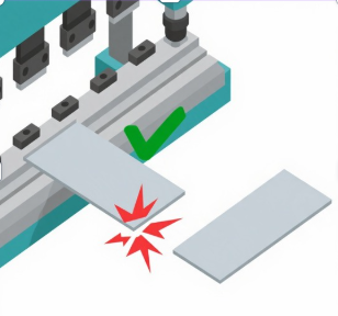
The ESA S650 always starts bending from the section with the smallest sheet metal width. Why does this matter? If you bend the larger side first, the workpiece may become too wide to rotate without hitting the machine posts or backgauges. By starting with the narrower section, you maintain clearance.
To optimize ESA S650 box bending, you can adjust the widths of your sections by changing the backgauge positions. If you find that the control is not starting with your preferred section, swap the order of the sections (by copying and pasting) or redesign the bend sequence.
Step 6 – Run a Simulation or Test Bend
Before running the full program, use the graphic preview (if available) to simulate the bends. Watch for any tool or workpiece collision with the machine frame. On a numeric program, you can step through each bend in semi‑automatic mode, checking the axis positions.
For physical optimization, run a test on a scrap piece of the same material. Measure each bend angle and flange length. Adjust the Y1 and Y2 lower dead points or the backgauge positions as needed. Keep a log of corrections for each box type – this data is invaluable for future ESA S650 box bending jobs.
Step 7 – Save and Name Your Program Carefully
Once your bends are correct and the sequence is optimized, save the program. Use a descriptive name that includes box dimensions and material, for example: “Box_200x150_H100_2mm_SS”.
If you plan to reuse the program with different material thicknesses, consider saving a template version and then using “Save As” to create variants. This saves time and reduces errors.
Common Optimization Challenges in ESA S650 Box Bending
Even with a well‑structured program, you may encounter issues. Here’s how to solve them.
Interference Between the Workpiece and Backgauges
If the workpiece hits the backgauges when rotating, the section with the smaller width should have been bent first. If it already is, try reducing the retract value (X‑axis retraction after bend) or use off‑center backgauge fingers. In the work data page, you can adjust the “Retract” parameter to pull the backgauges further away after each bend.
Inconsistent Flange Lengths on Opposite Sides
This usually happens due to cumulative error in backgauge positioning. For ESA S650 box bending, calibrate your X‑axis regularly. Also, use the same reference edge for all bends – typically the front edge of the sheet. Some operators prefer to use a stop block or laser guide.
Springback Variations Between Horizontal and Vertical Bends
If the material has directional properties (e.g., grain direction), bends on different sides may open up differently. Apply a small angle correction (e.g., +0.5°) to the problematic bends. Use the global correction factors in the material database to adjust for grain direction.
Section Not Executing in the Desired Order
The control forces the smallest width section first. You cannot override this directly. To work around it, create two separate programs and run them manually in the order you want. However, for true optimization, redesign your part so the smaller width section naturally corresponds to the bends you want first.
Preguntas frecuentes (FAQ)
Why can’t I directly enter the flat development for a box on the ESA S650?
The ESA S650 is designed for sequential bend programming, not for unfolding 3D models. You must manually create sections for each group of bends. This gives you more control over the bending order.
Can I bend a box with more than four sides (e.g., a pentagonal box)?
Yes. You would add additional sections – one for each group of parallel bends. The same principles apply: the control starts with the section having the smallest sheet width.
Conclusión
Optimizing ESA S650 doblado de cajas is all about understanding the two‑section approach, respecting the automatic execution order based on sheet width, and carefully adding or deleting sections as needed. By following the step‑by‑step guide – planning your dimensions, creating horizontal and vertical sections, verifying the bend sequence, running test bends, and applying corrections – you can produce perfect boxes with minimal scrap and cycle time.
Now that you know how to optimize ESA S650 box bending, I encourage you to try it on a simple box (e.g., 150x150x50 mm) with 1.5 mm mild steel. Create the two sections, run a simulation, and adjust the order if needed. Over time, build a library of optimized box programs for your most common products. For más ayuda, refer to the ESA S650 operator manual or contact our technical support team – we’re here to help you bend better and faster.


