Struggling to master your DELEM DA-69T press brake? This guide will help you understand the operation steps to ensure precise bending and improved productivity.
The DELEM DA-69T press brake provides advanced control features for accurate bending. Learn the step-by-step instructions for its optimal operation and how to avoid common mistakes that hinder productivity.
Now, let’s explore the setup process and key features to optimize your DELEM DA-69T press brake for seamless operations.
Operation overview and general introduction
1. The control unit
The control looks as follows:

The precise appearance of your control may differ.
Operation of the control is mainly done over the touchscreen. A description of the functions and available touch controls is given in the next sections of this manual, aside of the description of the specific functions.
Beside the touch controls the front of the control consists of an emergency stop, the handwheel and the start and stop buttons.
Special function keys, which can be mounted in the top panel of the control, have their specific description parallel to this user manual and will be supplied by the machine manufacturer.
This user manual focuses on the control software and related machine functions.
2. Front control elements
The frontpanel, beside display, consists of the following control elements:

3. USB connectors

4. Operation and programming modes
The control’s main screen looks as follows:
Depending on the navigation button which is active, the screen will differ. The above main screen will appear having the Products function active.
Just by tapping the various modes, the specific mode will be selected.
The structure of the main screen is as follows:
Title panel
In the top the title panel is always shown. In this area you can find logo information, which product is loaded, the selected products directory and (when activated) the service row. Also machine indicators can be found here.

Information panel
In the information panel all functions and visualisation related to the selected modus are displayed and can be found.

Command panel
The command panel is part of the Information panel and is the location where the controls related to the Information panel can be found.
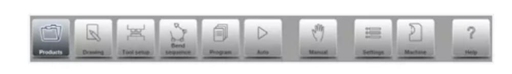
Navigation panel
The Navigation panel is the area where all the major modes can be found. This area is always visible. The controls, large buttons with icons, can be used to directly switch from one mode to the other.

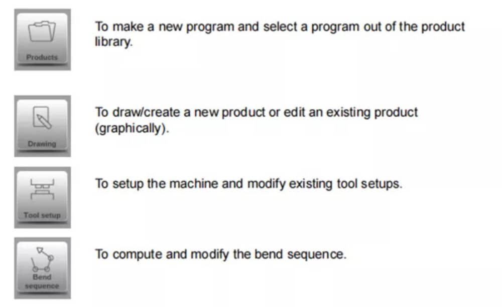
Explanation of the main modes / navigation buttons

5. Getting started
(1)Introduction
In order to obtain a bend program for a product, the control offers the possibility to create a product drawing and calculate a valid bend sequence for the product. With this information, a product program is generated.
This is done with the following steps:
● Go to the Products mode in the navigation panel and start a new product by tapping New Product.
● Enter the product properties and start to draw a 2D product profile in the Drawing mode.
● Check the tooling, modify or make a new set-up in the Tool Setup mode.
● Use the Bend Sequence mode to determine the bend sequence by calculating it or manually modifying it upon your own idea’s.
● When required modify the numerical CNC program via the Program mode.
● Tap Auto and press the Start button in order to produce the programmed product.
(2)Preparations
Before product programming can be started, the following preparations must be made.
● The correct material properties must have been programmed in the Materials library. You can find this on the Materials page in the Settings mode.
● The correct tools must be programmed in the Tool Library. Tools are necessary to create a CNC program. You can find the libraries for the different types of tools in the Machine mode.
(3)Create a drawing
The control offers the functionality to create a drawing of the intended product. With this drawing application, tap Drawing in the navigation panel, a 2D profile or 3D product drawing is created. At this stage, there is no calculation of bends or dimensions: any profile or drawing can be created.The drawing method on the Touch screen control is based on:
● Sketching
● Value setting
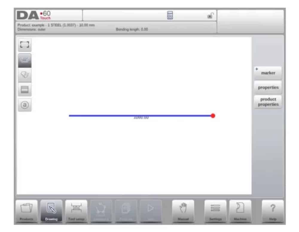
Sketching
The product as well as tool shape Sketching can be done by tapping on the screen in the different directions the drawing must have. The application will follow the tapping with drawing a line between the indicated points. The last point of the design will show always a big red dot.
When the drawing dot is on the screen you can hold your finger on this position and move the finger across the screen to move the connected line in another required direction or make the line length longer. This method is the so-called ‘Dragging’ facility. The length and angle value will be visible on the screen and can be adjusted to be exact or close to the requested value.
Value Setting
Once the product or tool is drawn in the Sketching method the exact values of line lengths and angles can be optimized by the Value setting method. Just tap 2 times on the value of the line length or angle to change and the keyboard will pop-up. The value can be entered in 2 ways
of confirmation:
● Enter function
● Enter-Next function
The Enter function will close the keyboard after entering the value. The Enter-Next function will enter the value on the line or angle to change and the keyboard will remain opened for the next programming step.
In case the typed value is erroneous, the “undo” button right from the input field can be tapped to return to the original value or the backspace key on the keyboard to delete the last typed character.
Zoom Function
By pinching the screen with two fingers simultaeously one can zoom in and out on the drawing, tool or machine visualisation. By spreading fingers the system will zoom-in, by bringing fingers nearer to each other the system will zoom-out.
Fit-To-Screen
In the command icons on the side of the screen you will find a Fit-To-Screen function. This can be used when the drawing size is not clear in picture. Just tap once and the complete drawing will be sized to fit the drawing screen.
Panning
With simultaneous touching of two fingers and draging them over the screen (sliding in the same direction) one can pan the object in 3D view. In 2D a single finger will also enable panning.
Rotating
In 3D, rotating the product, tool or machine visualisation, can be done with a single finger sliding over the screern.
More information about this can be found in chapter 3.
Features of the drawing tool
● Graphical design of product shapes in 2D and 3D (if available)
● Scaled sheet thickness
● Auto scaling
● Horizontal and vertical projected dimensions can be entered
● Real scale tool design
● Various machine shapes (pressbeams and tables)
● Changing of lengths and angles
● Adding or deleting of bends
● Special bend features can be applied
● Hemming bends can be programmed
● Bumping bends can be used for big radius
● Existing products can be copied, changed and stored as a new product
● Closing dimension or highest precision tolerance selection
● Connecting 2D programs for 3D-production
(4) Determine bend sequence
When the product drawing is completed, the control offers Tool setup mode to program the exact tool set-up as it is organised on the machine. After this you can select the Bend Sequence mode to determine and simulate the required bend sequence.
In the Bend Sequence mode, the control shows the product, the machine and the tools. In this menu the bend sequence can be programmed and checked visually. When a bend sequence has been determined, the CNC program can be generated.
More information about this can be found in chapters 4 and 5.
Bending sequence computation
• Automatic computation for minimum production time
• Interactive bend sequence determination
• Manual bend sequence determination
• Collision visualization of product with tools and machine
• Free tool and machine shape selections
• Assignments of turn times, backgauge speed etc.
• Blank length computation
• Production time indication
• Bending sequence simulation
• Programmable finger positions
(5) Numerical program
The Program menu gives access to the numerical program and values of the active product.
There are two possibilities to create a CNC program:
• enter a numerical program, started via Products mode, tap New Program, step by step;
• generate the program from the graphical bend simulation started via the Products mode, tap New Product, via the Drawing mode. (see: Drawing mode; product drawing).
If the program is entered by hand, there is no collision check. All program values must be entered manually. The program depends on operator experience.
If the program is generated from a graphical bend sequence, the program can be visualised during production. A generated program can be edited according to operation needs.
More information about this can be found in chapter 6.
When a drawing has been completed with a bend sequence, and the program is stored, the program is post processed and the numerical program becomes available.
The system automatically computes :
• Necessary force
• Machine adjustments such as:
• Y-axis position
• Decompression
• X-axis position
• X-axis retract
• Y-opening
• R-axes
• Z-axes
Axes positions are calculated according to the machine configuration.
(6) The Auto menu and Manual menu, production modes
A product program can be executed via the Auto mode. In Automatic mode, a complete program can be executed bend after bend. In the Auto mode the Step mode can be selected to have each bend started separately.
The Manual mode of the control is an independent production mode. In this mode, one bend can be programmed and executed. It is typically used to test the behaviour of the bend system.
More information about this can be found in chapters 7 and 8.
(7) Back-up data, external storage
Both product and tool files can be stored externally. Depending on the configuration, these files can be stored on a network or on a USB stick. This facilitates a back-up of important data and the possibility to exchange files between Delem controls.
More information about this can be found in chapter 9.
6. Programming aids
(1) Help text
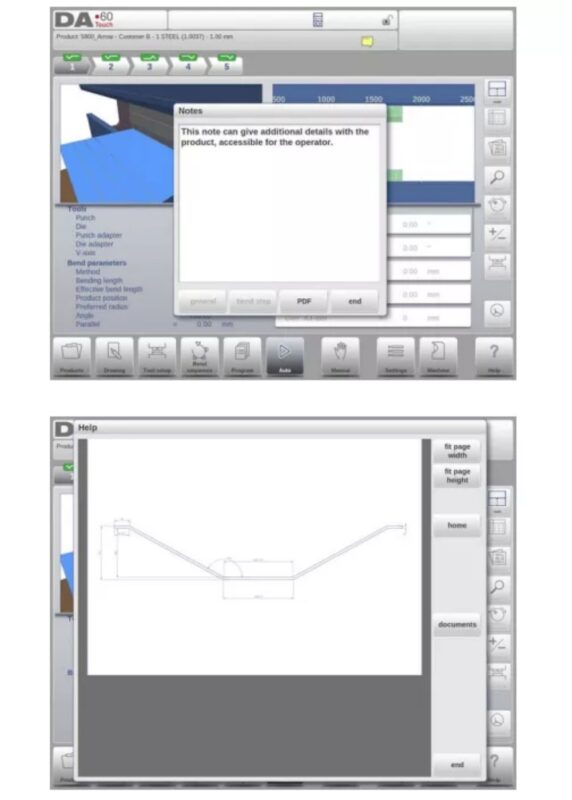
This control is equipped with an on-line Help function. When the Help-button in the navigation panel is pressed context sensitive help will be provided.
To activate a help window for a parameter tap the Help button in the navigation panel.
A pop-up window appears with information on the active parameter.

This Help window contains the same information as the Operation manual.
The help window can be used as follows:
You can scroll through the text sliding one finger in the desired direction. By tapping on the lower or upper part of the screen Previous Page / Next Page can be used to browse through the help text.
The Index function helps to jump to the table of contents. Hyperlinks in the table help to directly navigate to the desired topic.
Tap End to close the Help window.
(2) Listbox functionality
Several parameters on the control have a limited number of possible values. When selecting such a parameter, by tapping the parameter line on the screen, the list of options will open up near the position where you tapped the line, and the desired value can be selected.

To undo the selection and the opened listbox, tapping outside the box will make it close without changing the selected parameter.
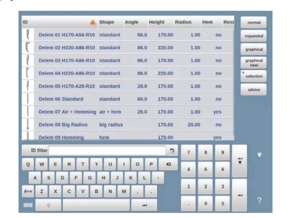
(3) Filter, live search, auto filter
In some modes a list of entities is offered (products, tools, materials, etc.). An example of such a menu is the Products mode (product selection). To search a particular product or tool, the filter function can be used. Press the command button Filter, type a part of the ID in the enter field. Automatically, the list is limited to those items that contain the typed part.
Multiple search parts can be separated by <space>.
To close an open filter screen use the keyboard-close button on the right side next to the keyboard.
Auto filter
In addition to the filter function the column headers of eg. the tool selection tables and the product selection table have ‘auto-filter’ functionality.
When tapping the column header one can sort the list based on that specific column. The triangle in the header is shown as an indication of the sort order.
When tapping a header with auto-filter functionality a list box will be shown automatically offering the possible options for filtering, derived from the available entries in that column. E.g.
when using this in a die selection, the V-opening can be filtered to the desired value as searched for. The list will only show dies complying the set filter.
Filters can be switched of in a similar way. The list also offers a remove filter function.

(4) Navigation
Within some modes, the program screens are divided into tabs.
The tabs can easily be selected by just tapping them. When a tab is not completely visible or not visible at all, just by dragging the tab row horizontally, the desired tab can be “pulled” in sight and be selected.
(5) Text input and editing
The cursor can be used to enter a specific value or text within an existing input. Just tap at the desired position to do so. The cursor will appear and input will be added there.
E.g. in Edit notes, where multiple lines can be entered Enter is used for linefeed. Cut, Copy and Paste are offered on the keyboard for editing convenience. Undo and Redo can also be used within this editor.

The keyboard can be shown or hidden in this multiline editor using the arrow key in the lower left corner.
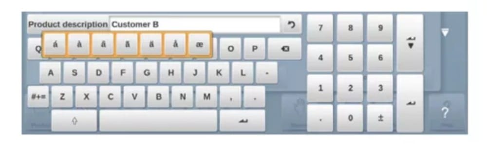
(6) Typing alphanumeric characters vs. special characters
Both alphanumeric characters and special characters can be used throughout the control. A full on-screen alphanumerical keyboard will pop up when required.
When editing a field which is pure numeric, the alphanumeric characters will be “greyed-out” and only the numerical keypad can be used. For fields which enable to use alphanumerical strings, the keyboard is completely available. Special characters as ? % – can be found using the special character button on the left-lower side of the keyboard.
Special characters (like á, à, â, ã, ä, å, æ) are supported by the on screen keyboard by keeping a character (like ‘a’) pressed.
(7) Calculator
The CNC control is providing a “desktop calculator” available for the operator.
At the top of the screen the calculator icon can be used to switch to calculator functionality.
The keyboard area provides calculator functions which can be used autonomously. Standard functions (add, subtract, multiply and devide) including percentage, square root, square and memory functions are available.
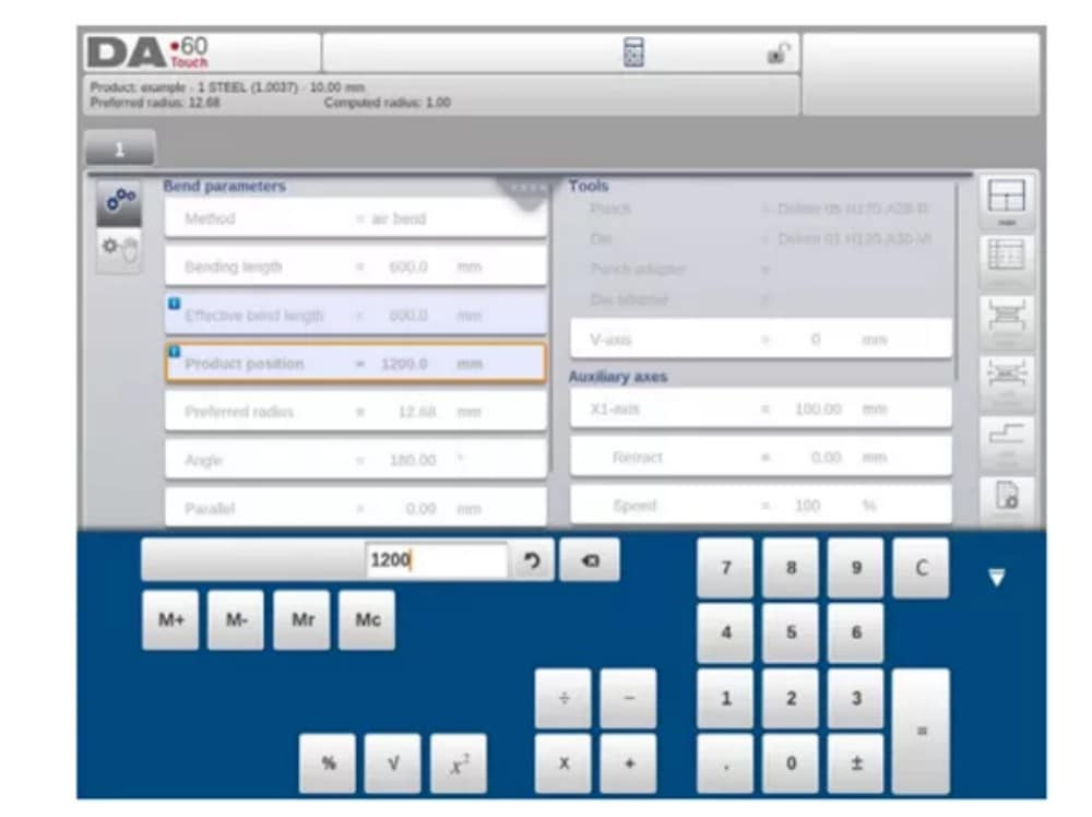
In case calculations should use parameter values as an input, and results as an output, one can switch to the calculator from the parameter entry. This will bring the parameter value to the calculator, and the result back to the input line.
No cutting or pasting is necessary. Only when entering and confirming the calculated value in the parameter entry line, it will be used forward.
(8) Messages centre
When messages are displayed coming from PLC, Safety systems, LUAPs or the Sequencer, these messages can be ‘send’ to the ‘Messages centre’. When a message is displayed simultaneously the message centre symbol is shown in the top row of the page header, next to eg. the calculator and keylock symbol. When tapping this message centre symbol the messages are taken from the screen, giving way for normal programming and editing.
When tapping again the actual messages are shown.
When messages are in the background, the message centre symbol has an extra indicator to show new incoming messages which are not yet shown.
(9) Network
The CNC control is equipped with a network interface. The network function offers the operators the possibility to import product files directly from the network directories or to export the finished product files to the required network directory
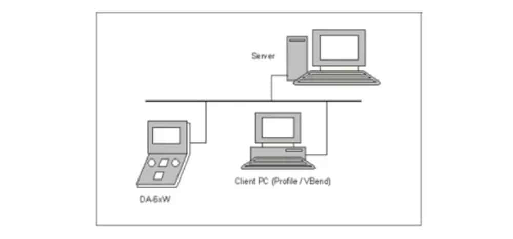
Chapter 9 about backup/restore in Settings mode contains more information about networking possibilities.
(10) Keylock function
To prevent for changes to products or programs, the keylock function offers the possibility to lock the control.
There are two levels of locking the control. Program Lock and Machine Lock.
• In Program Lock, only a product can be selected and executed in Automatic mode.
• In Machine Lock, the machine is locked and the control can not be used.
To lock a control just tap the lock symbol in the top of the screen. Depending on the code which is used, the control will be in Program Lock or Machine Lock. Program Lock wil show a closed lock in grey. Machine lock will show the same lock but colored (red).
(11) OEM function panel
Depending on machine manufacturers implementation, the upper right corner of the screen can be used for special indicators.
To access functions related to those indicators, the OEM function panel can be opened by tapping this corner of the screen.
(12) Software versions
The version of the software in your control is displayed at the System Information tab in the Machine menu.

Products, the product library
1. Introduction

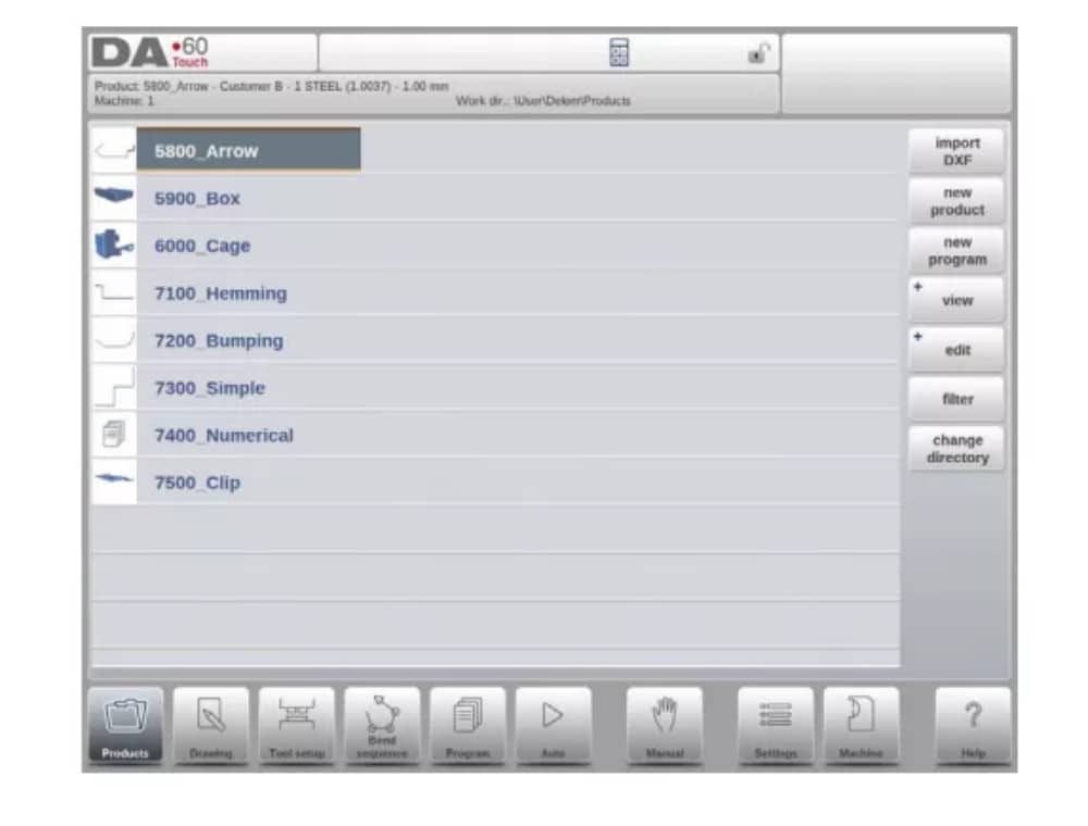
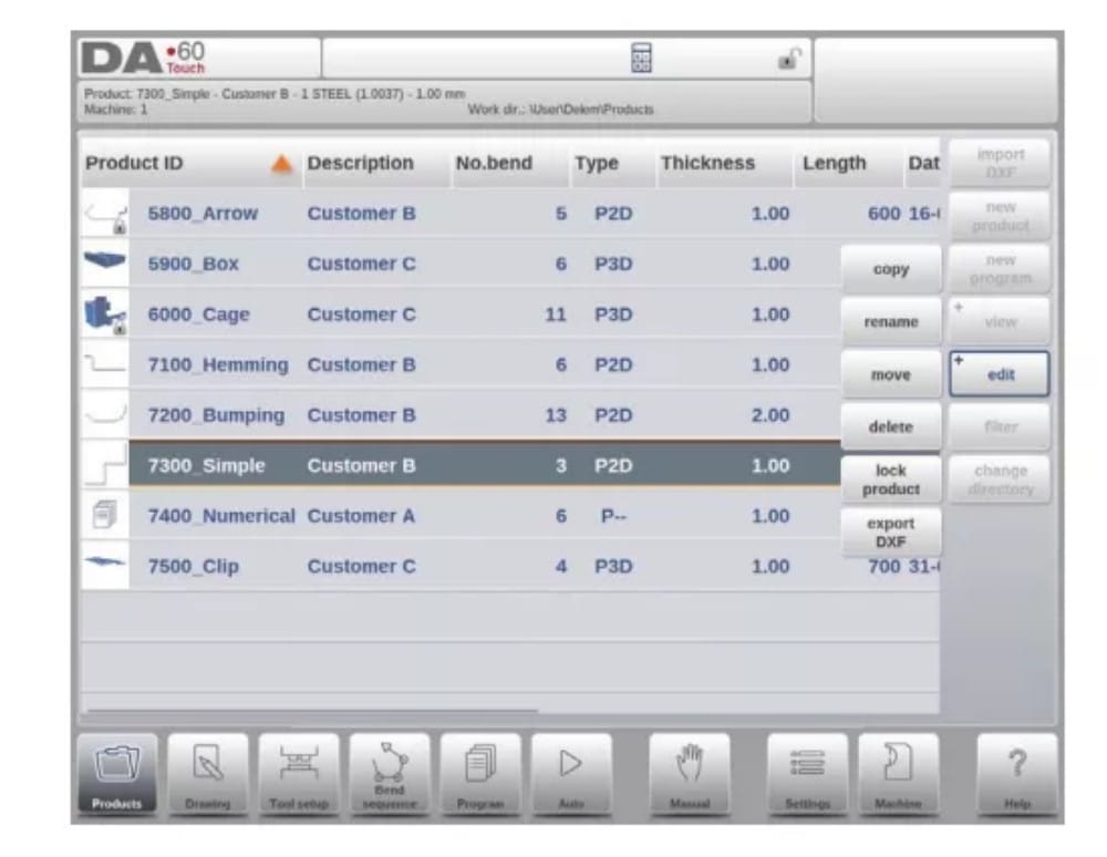
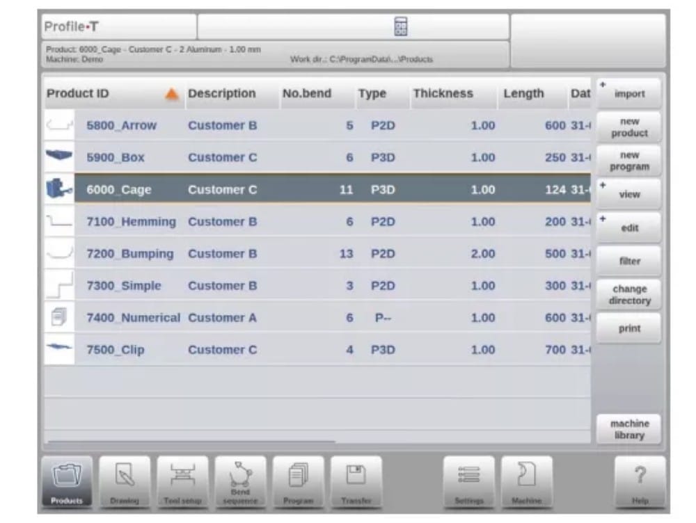
(1) The main view

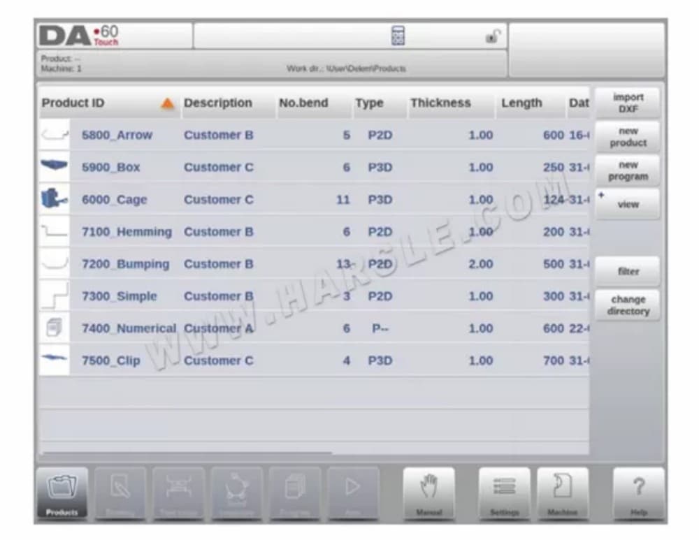
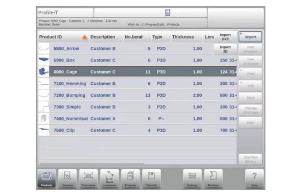
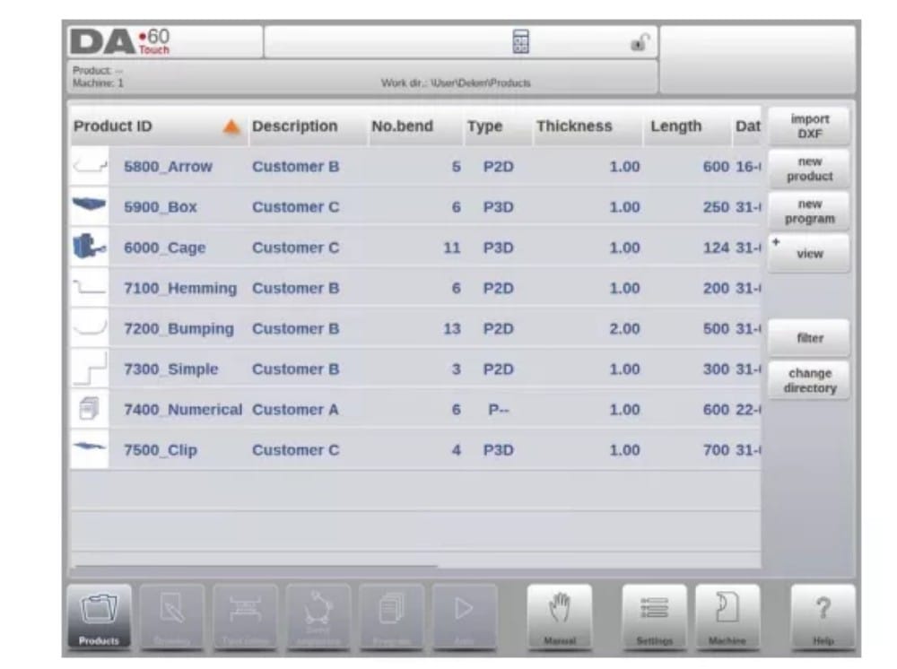
In Products mode an overview is given of the program library on the control. In this mode a product program can be selected (loaded). After that a program can be modified or executed.
Each item in the list consists of a thumbnail of the graphical product (for numerical programs a symbol is shown), its Product ID, the Product Description, the Number of bends in the product, what kind of product it is (Type) and the Date it was last used or modified.
The Type indication of the product shows following types of products:
(2) Product selection
To select a product a single tap will do. The product will be selected and loaded into the memory. From here production can be started by tapping Auto. Also navigation can start through the Products Drawing (if existing), its Tool Setup, the Bend Sequence and the numerical Program of the product.

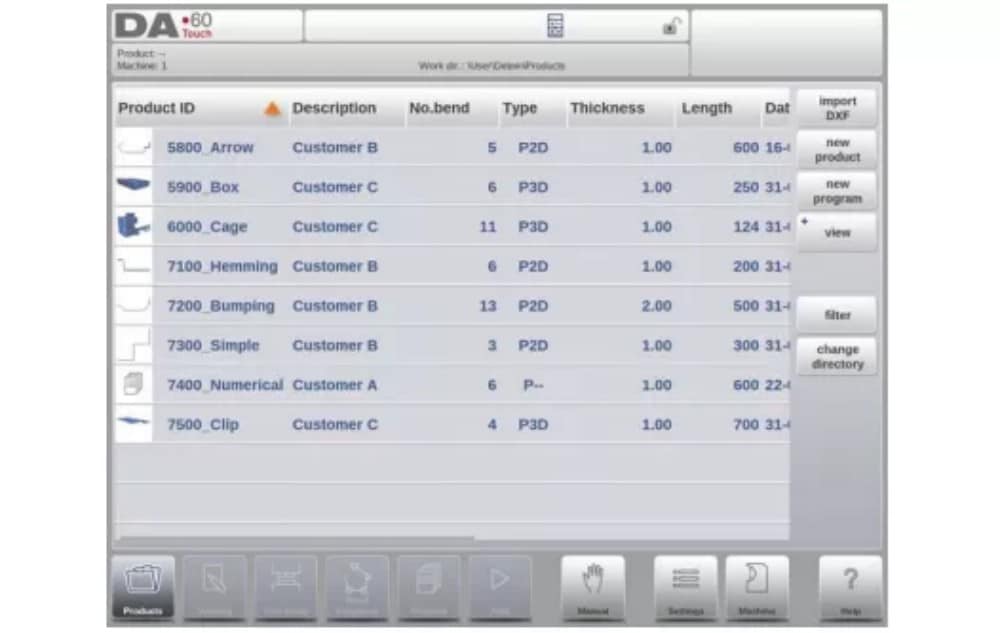
(3) New Product, starting a new graphical product
To start a new graphical product tap New Product.
After New Product is chosen, the programming of a new product starts with its general details like Product ID, Thickness and Material.

(4) New Program, starting a numerical program
To start a new numerical program tap New Program.
After New Program is chosen, the programming starts with its general details like e.g. Product ID, Thickness and Material.

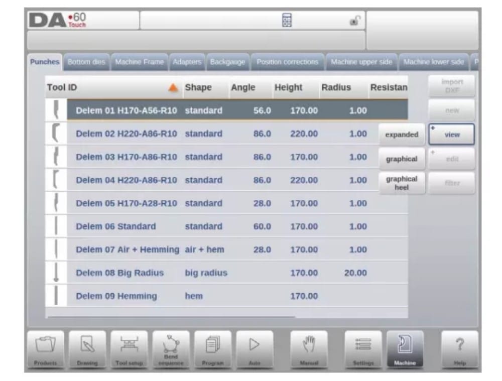
(5) Views
To view the products as a simple list, or completely graphical, the View function can be used.
By tapping View one of the three view modes can be selected.

(6) Edit, Copying and Deleting a product or program
To delete a product in the Products mode select a product by tapping it. It will be selected.
After that tap Edit and use Delete. To finally delete it confirm the question. To delete all products and programs at once, tap Delete All.

To copy a product select a product or program and tap Edit and use Copy. After this the name of the product can be programmed and the copy will be done. The product will appear in the same directory. The copied product will be an exact copy including tool setup and bend sequence if available.

(7) Product Rename and Move
Products can also be moved and renamed.This can be done in one single step: Move moves a product to a new directory, Rename allows the user to give it a new name within the same directory.
To move or rename a product select a product or program and tap Edit and choose Move or Rename from the list. For Rename a new name can be given. The product will appear in the same directory. For move a new location can be selected. The copied product will be an exact copy including tool setup and bend sequence if available.
(8) Product Lock/Unlock
The product Lock/Unlock function provides a simple method to prevent accidental changes to finished programs or products. In this way products which have been tuned and found to be good cannot be changed unless the product is unlocked.
When tapping on Edit the Lock Product / Unlock Product feature can be switched for each product or program.
(9) Filter function
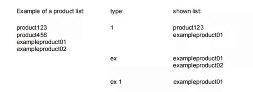
To make finding products easier the filter function enables live searches through-out the Products mode.
When tapping Filter, the filter screen will show. By typing the desired filter string, optionally devided by spaces, the live search will start.
Optionally a different view can be selected. Also the specific property on which the filter is applied can be changed by using Selection.
Selections can be done on Product ID, Product Description, Type, Thickness, Length or Date.
You can either enter a complete name or number or only a part of it. If you enter part of a name and this part occurs in several product names, the control will show all product names that contain that part. It is also possible to enter a combination of name and number.
See also section 1.6.3 about Filtering and ‘Live search’.

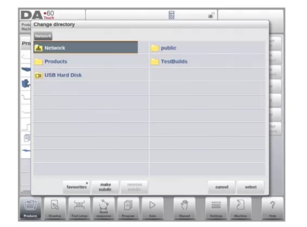
(10) Change directory
To change to a different product directory, or to add a new product directory, tap Change Directory. When an obsolete directory must be removed, select the directory and tap Remove
Directory. When a desired directory is reached, tap Select to jump back to the Products screen which will show all products in the directory. The active local directory name is displayed in the header.

(11) Network product selection
When a network directory has been mounted in the control this mounted directory can be found under Network. Network is available next to the Product directory when using change directory. The name of the mounted drive indicates availability for product selection and
storage.
The network directories can be navigated thru in the directory browser. Directories can be selected, added and removed and products can be selected. When a desired directory is reached, tap Select to jump back to the Products screen which will show all products in the directory. The network directory is now the active local directory. Its name is displayed in the header of the screen.
When you leave the product selection menu the control remembers the active subdirectory and the active product (if a product was selected) until another directory or product is selected.
While working with a “read-only” network, or when the network connection is interupted, the product will be saved in subdirectory “Recovered”. This can be found as a subdirectory under Products.
By tapping the Refresh button (on View) in Products mode the product library that is displayed on the screen is refreshed, which can be useful when working from a network location.
2. The DXF import option
An alternative for drawing the desired product in the control, the control can also import an externally generated CAD-system output file. This chapter will explain the use of the DXF converter to import DXF files and its functionality.
The DXF import option is started with the command button above New Product. Import DXF opens a file selection browser to select the DXF file.
Files can be located on eg. a USB stick or on the network directory. One can browse to the location and select the file.
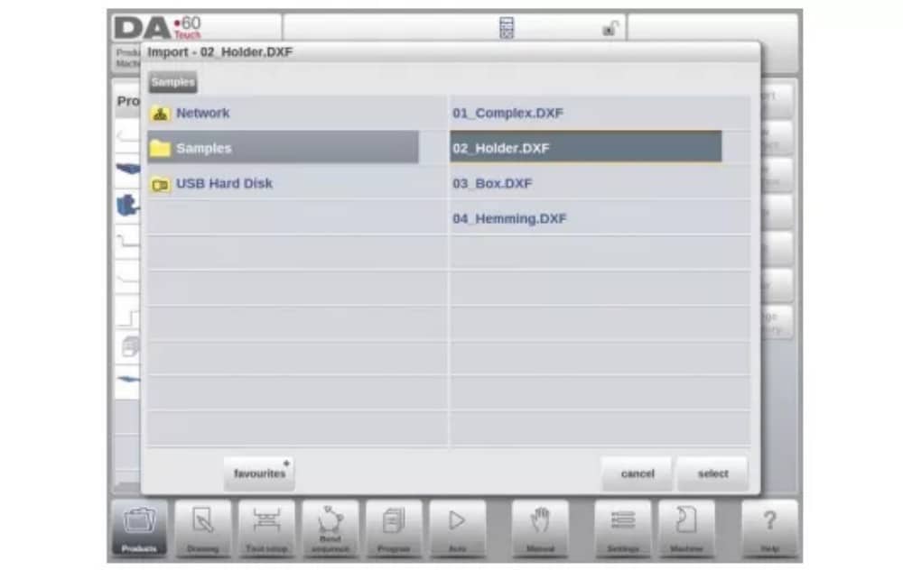
For the DXF file to be imported it is advised to create the original drawing as accurate as possible. Bend lines should be connected to contour lines to obtain an accurate product drawing. If this is not the case, the DXF Converter can correct small errors.
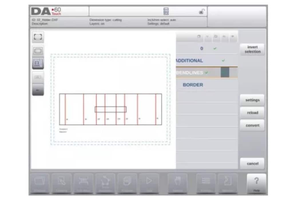
After selecting the DXF file the DXF import function window will open showing the DXF file. If this is with layer selection on, the drawing will be dashed, since no line is yet assigned to what it means.
(1) Product drawing dimensions
The drawing file can be organised in two ways:
• projection dimensions;
• cutting dimensions.
These ways are described in the following subparagraphs.
During operation in the DXF converter, it is possible to switch between cutting dimensions and projection dimensions. This can be done in the DXF conversion settings.
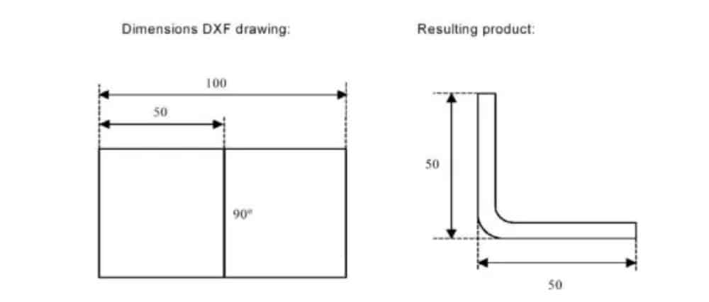
Projection dimensions
In this situation all product sides and bend lines have the length of the resulting product. The drawing does not represent the real size of the sheet that must be bent, but is merely a representation of how the sheet is to be organised into bends and surfaces. When such a
drawing is loaded and converted, the converter will construct a product drawing with exactly the same sizes as are present in the original drawing. Later on additional information is added about material, sheet thickness and product dimensions. It is left to the control to create a CNC program with proper axes positions that will result in a product as intended.
(2) Bendlines and Layer selection with Line assignment
For a proper conversion, the assignment of specific product properties to lines in the DXF is important.
Depending on the content of the DXF, the bendlines, contour and additional text information can be assigned layer by layer. In case layer selection is set off, the bendlines are being searched for automatically.
Bend line information
With the bendlines the angle information can be defined via text near the line. The text labels,
to be configured in Settings::Labels, can be used as follws:
• Default: normal air bending with a positive or negative value
• Hemming: an H followed by a positive or negative value of the pre-bend angle.
• Radius: an R followed by the value of the radius.
Definition:
• positive value: the flange bends upwards,
• negative value: the flange bends downwards.
Product information
Beside the actual product drawing a DXF drawing can contain other information, such as manufacturer name, dimension lines, product description etc. If this information is organised in other layers than the product drawing then this information can be filtered out by selecting only certain layers for conversion. Otherwise, it possible to remove unnecessary information in the converter program before conversion of the drawing is started.
Layer selection
Depending on the DXF import settings, which can be entered from the mainscreen, layer selection can be set on or off.
In case of layer selection on, the layer property list visualisation can be switched. The buttons in the left top corner enable this choice. Following paragraphs describe the difference between
Layer selection switched on and Layer selection switched off.
(3) Conversion
When the assignments have been set properly, conversion can be executed by tapping the Convert button.
The conversion preview will be shown when there are warnings or errors.
During conversion the DXF drawing is represented by lines like contour line, bend line and inside contour lines. Colors indicate the property for the line conversion.The lines of the product drawing will have different colours after the conversion. Every colour has its own meaning:
• Blue: Contour line, this line is a part of the outer contour of the product.
• Red: Bend line, this line is a bending.
• Green: Inside contour, this line is a part of the inner contour of the product.
• Black: Assigned texts will be shown in black.

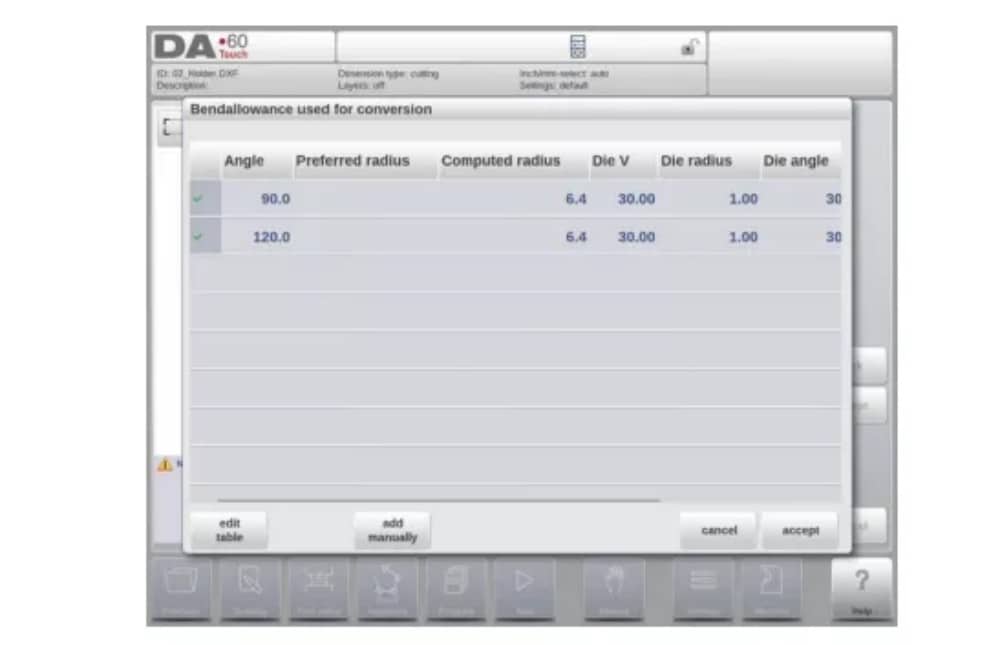
(4) Converting cutting dimensions, with bend allowance info
At the last stage of converting a DXF with cutting dimensions, the bend allowance which has been used during unfolding, needs to be reused in the conversion.
Therefore the conversion of cutting dimensions will always use the bend allowance table of the control and it will check if for all bends bend allowance information is available.
In case there is just one set of bend allowance parameters available for each bend, this will be used. The bend allowance pop-up will show the angles from the product with the found bend allowance. If more entries in the table can be valid, one needs to select the appropriate bend allowance line. The prefered and calculated radius can be helpful in this selection.
Adding Bend Allowance information manually
In case the bend allowance information is given with the DXF cutting dimension drawing, included in the DXF or as separate info, there is the possibility to manually enter this information.
When a DXF is imported and the bend allowance value per bend is included (based on the bendline info) these values are imported and used with the desired bend. The control will use this as an input which overules the bend allowance calculation or table search of the control.
If this information is entered during the DXF conversion, this will work equivalently, bypassing the controls calculation or table search.
If the desired bend allowance information is not present from the table, one can also manually add the information just before actual converting. In case the bend allowance is not given before or during the DXF conversion this will be automatically prompted. One can select either to select from excisting entries from the bend allowance table, or enter bend allowance just for this conversion.
To enable the function of programming bend allowance information in the Drawing function of the control (bend property) this needs to be switched on in the product properties. This is automatically done in case of importing.
(5) DXF Settings
In the DXF converter settings the conversion parameters can be configured. It is possible to store multiple settingsfiles for specific drawing types. Save as and load functions are available.
Conversion parameters

3. The 3D import function (Profile-T3D offline only)
An alternative for drawing the desired product in the application is to import an externally generated CAD-system file. With the 3D import function Profile-T3D can import the generic .IGES and .STEP files.
This chapter will explain the use of the 3D import functionality for.IGES and .STEP files.
(This functionality is solely available in Profile-T3D)
The 3D import function is started via the Import command button above New Product. Import 3D opens a file selection browser to select an .IGES or .STEP file.
(1) Conversion

The conversion can be started by tapping Convert. This will start the interpretation of the 3D design into a product with bendlines and sheetmetal specific characteristics.
The application will show the product with the designated bendlines.

In case the converter does not find any imperfections the conversion is previewed and one can finalize the conversion with tapping Accept.
From here the product is converted and shown in Drawing mode.
One can continue with tool selection and bend sequence programming.

The 3D CAD file requirements
For the .IGES and .STEP files to be imported it is important to meet the constraints for sheet metal product designs. The constraints are available upon request at Delem.
The 3D file to be imported must of course be generated with the objective to design a sheet metal part which can be processed on a press brake.
4. The DXF contour export option
As part of the DXF-option the Export DXF function, on Edit in Products mode and on Transfer (Profile-T), enables the export of any product including the bend deductions as a contour. This contour is stored as a DXF and holds the cutting dimensions.

Product drawing
To start a new product drawing, choose New Product in the product library
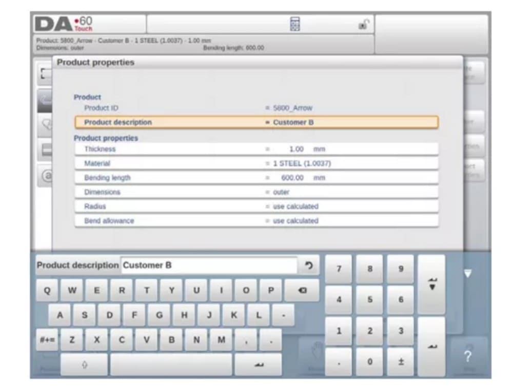
When a new product drawing is started a screen with general product properties appears.
First these properties, general data, should be set before starting with the product drawing.
(1) Add Notes
When Edit Notes has been pressed, a new window appears in which you can edit the text about the current product. The possible characters are displayed on the keyboard.

2. 2D product drawing
(1) Introduction
After entering the general product data the drawing screen appears.
In the upper information row you will find the information about product ID, product description, inside/outside dimensions selection and actual product directory.
Now you can create the profile of the product. It is possible by using your fingers to tap and create quickly the product in ‘sketch’ mode. After that the real product dimensions and corresponding values can be entered by using the keyboard.
It is also possible to directly enter the angle of the bend followed by the length of that side by using the keyboard and the Enter button. The properties are prompted in the input bar of the screen on the keyboard panel. This procedure continues until the product has the desired profile.
The product data can be changed by selecting Product Properties. The properties of the product angles and lines can be changed by selecting Properties.
Tool configuration
1. Introduction
2. Standard procedure
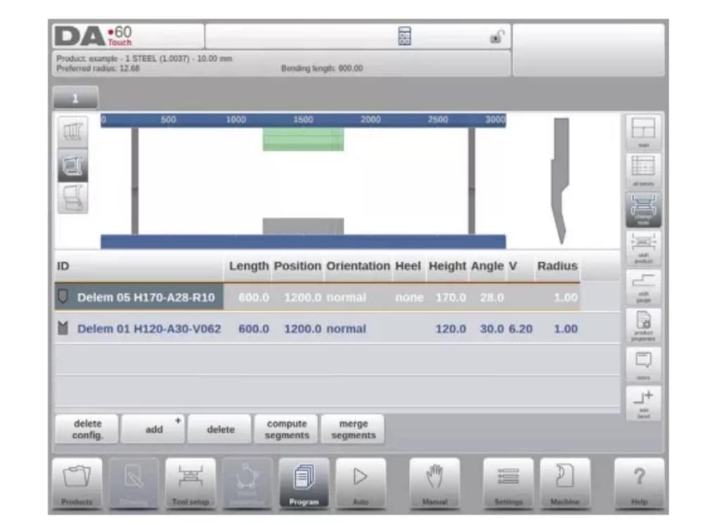
When the function Tool Setup has been activated, the screen shows a front view of the machine set-up in the upper half of the screen. In the lower half of the screen, the tool data is displayed. In this screen, the placement of tools in the machine can be programmed.

3. Tool selection
When starting a new tool configuration, the machine opening is empty

Select Add to add a tool to the configuration; punch, die or adapter (if enabled)

When a tool has been chosen (e.g. a punch), it is placed in the machine with maximum available length.

After a tool is placed, the tool ID can be changed by selecting the Punch ID in the screen and tapping on the List view.
4. Tool segmentation
When using segmented tools, from which desired sized tools can be composed, the control can support this and can help to generate the appropriate segmentation.

In below paragraph the functionality for segmentation is explained, including the use of the three views on the tool setup. Next to the Tool Setup screen the ability to have segmentation features available is depending on the programmed segments for each tool. This
programming can be done in Machine mode under the Punches and Bottom dies libraries.
More on programming of segments in the Tool library can be found at the end of this paragraph.
From within the Tool Setup screen there are three available view modes. With the selection buttons on the left side of the machine front view following views can be chosen:
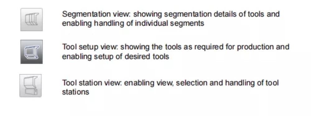
5. Segmentation of individual tools
After the proces of setting up the desired tools for the products to be made, the Bend
Sequence mode can calculate the most efficient bend sequence.
Upon desire the tools can be segmented, helping in the selection of the segments creating the correct tool length.
The tool segmentation function automatically calculates the required segmentation and uses the assignments “maximum inter tool distance” and upon choice the “tool length tolerance” for finding the best solution

6. Station selection and repositioning
The third Tool Setup view is the Station view. In Station view the complete toolstations are highlighted when selected, and can be repositioned by programming an alternate position or dragging to the desired new position in the machine.
A toolstation is automatically defined when there is an overlap from punches with dies. This, meaning that a toolstation is considered a station when e.g. there is an exact position of punch and die opposite of each other. When there is a shifted position but still overlap in
between punch and die, this is still considered a tool station. Even when two punches are opposite of a single die, which can be useful bending constrained bends, this is considered a toolstation. These stations can be repositioned without losing their relative positioning.

Station view is not changing anything to the tool details.
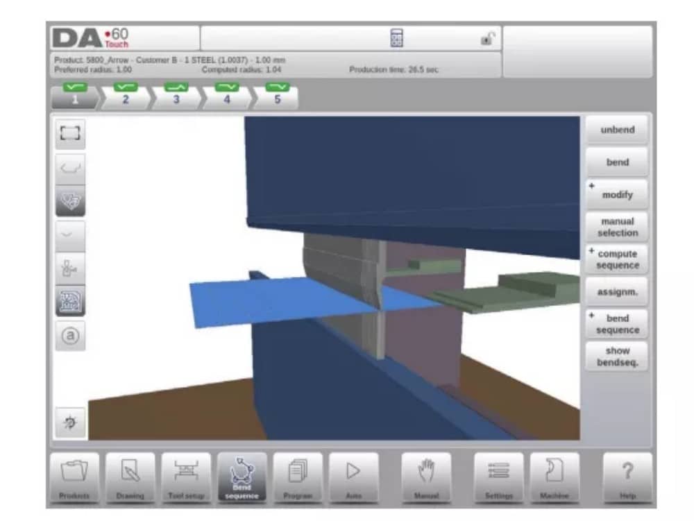
Bend Sequence
1. Introduction

When a tool configuration is available, the bend simulation can be started to determine a bend sequence for the active product. The bend sequence determination is started by tapping the navigation button Bend Sequence.

The bendsequence determination can be realised by automatic calculation starting with the bent product. It is also possible determining the sequence manually starting with the flat
product, not using the automatic calculation.
In the bendsequence screen the product appears between the tools in a possible last bend position. When starting the simulation, the product is shown in its final state. In order to obtain a bend sequence, the product must be unfolded from the last bend to the first. This can be done with the available function keys.
When it is prefered to start with a unfolded product to manually chose the bendsequence, this can be chosen under the command button Bend Sequence.
(1) View select
Within the bendsequence screen views can be switched upon required choice.
The view functions are located oposite of the command buttons in the main screen.
View functions

(2) Bend selector
Within the bendsequence screen bends can be selected and navigated thru with the bend selector. In the top of the screen the number of bends is indicated with preliminary bend selectors. After completing the bend sequence, these are all colored, active and show a turn indicator.

From then bends can be tapped to easily to select the desired bend data. In the bend selector the turn indicator will be displayed showing green, yellow or red colors to indicate the level of complying the assignments of the bend sequence.

2. Unbend product
In order to generate a CNC-program the bend sequence must be known. There are two ways to achieve this:
• Press the function key Compute. The control will automatically compute the quickest
possible bend sequence for this product.
• Press the function key Unbend repeatedly, until the product is completely unbent.
When the product is completely unbent, press the function Bend sequence and Save to generate and save the CNC-program.

3. Manual selection of bends
Normally the control proposes the next (un)bend in a sequence. This is computed by the control depending on the programmed assignments and of course the product shape and applied tools. For various reasons it can be necessary to choose another bend for the bend sequence. The bend sequence can be changed/determined through the function Manual
Selection. When the function Manual Selection has been choosen, a new window is opened.

4. Assignments
(1) Introduction
The Assignments are parameters with which the bend sequence computation is controlled.
The assignments screen is opened from the tool configuration screen with the function key
Assignm.
Automatic bend sequence computation works with several conditions in order to find an optimum between a minimum production time, handling possibilities without product/machine and product/tool collision.
In order to find one of the optimums you must program several computation parameters with which the bend sequence can be computed. Some of these parameters are machine-related and some are related to product accuracy, handling possibilities and turn times.
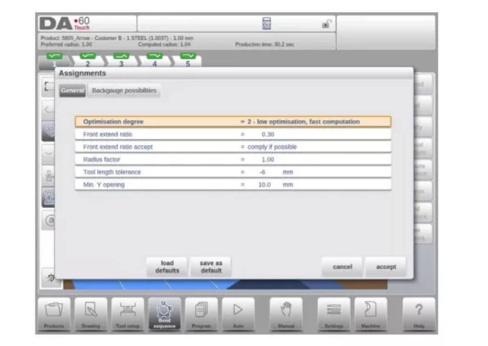
(2) Assignments – general
Optimisation degree
Range 1-5.
The number of alternatives to be computed for each bend must be entered here.
The higher this number the more alternatives are to be examined by the control, so the longer the computing time will be:
1 – lowest optimisation, fastest computation
2 – low optimisation, fast computation
3 – medium optimisation, medium computation
4 – high optimisation, slow computation
5 – highest optimisation, slowest computation
(3) Assignments – Backgauge possibilities

5. Show bend sequence
When the function Show Bend Sequence has been pressed, a graphical overview of the bend sequence is shown.

This option can be called at any time after the first unbend has been made. The graphical overview displays the determined bends as well as the not yet determined bends (question mark sign).
Each image in the overview can separately be enlarged or reduced with the available functions. The images can also be rotated by finger movement.
Product programming
1. Introduction

To edit an existing CNC program, select a product in the Products overview and select the navigation button Program. When starting a new program, select New Program and after giving in the main product properties and tool setup, the system will automatically switch to Program.
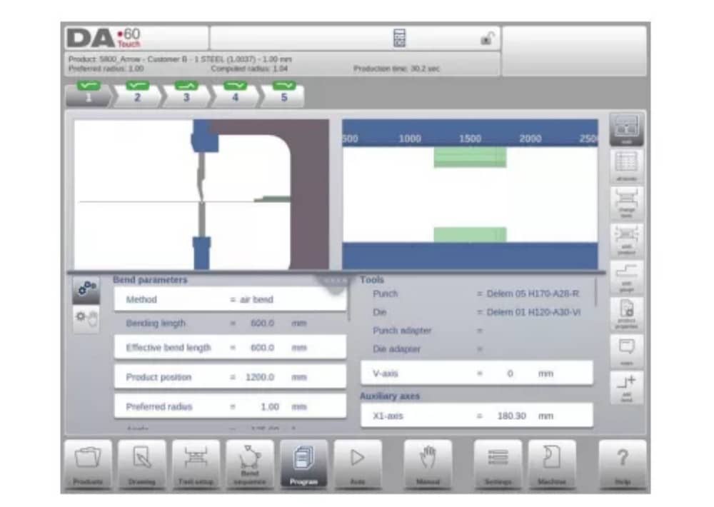
In both cases, a screen as shown above should appear. Programming and changing data is done in the same way in both cases.
The main screen shows the existing numerical program or, when starting a new program, the first to be programmed bend. The bend selector in the top of the screen can be used to navigate thru the bends. The indicated bends can be tapped to easily select the desired bend data.
At the side of the main screen views and functions are indicated with command buttons.
Functions
Following modes / functions are available:

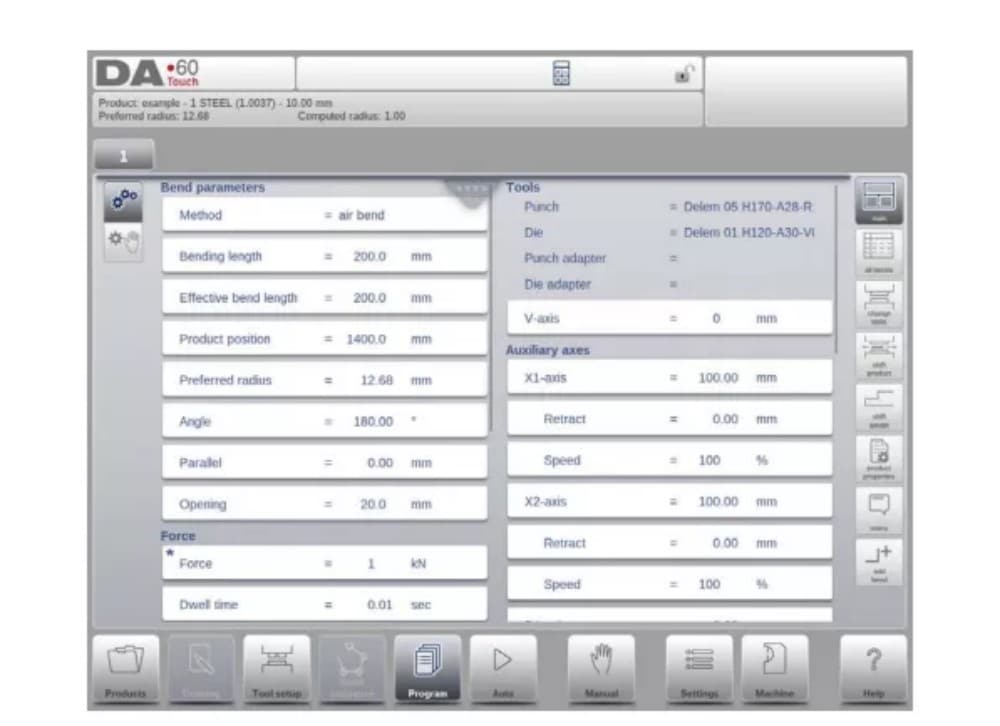
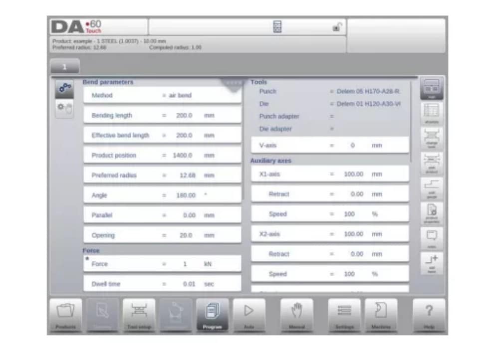
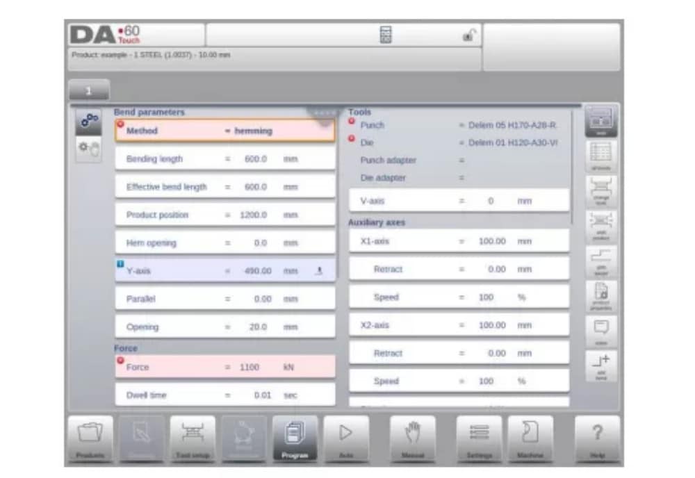
2. Program mode, parameter explanation
The main screen shows the available bends and from this main screen, from every available bend, specific paremeters can be viewed and edited.
The product ID and product description are displayed in the top row on the screen.
In case of a graphical product graphical information can be shown as well.
(1) Bend parameters
Bend methods

(2) Force
Force
Maximum adjusted force during pressing (automatically computed).
Dwell time
Holding time of punch at bending point.
Speed
Speed
Working speed (pressing speed). Initially, the value for this parameter is copied from the parameter Default Pressing Speed in the Settings mode.
Functions
Repetition
0 = bending is skipped
1 through 99 = the number of times this bending will be repeated.
3. Edit / view modes
(1)All Bends
When the function All Bends has been pressed, a complete overview of the bends appears.

From within this screen, the complete CNC program can be edited. All bend parameters can be edited within the table and bends can be swapped, moved, added and deleted.
The available columns can be scrolled by finger movement / swipe.
(2) Change tools
To change the tools the Tool Setup menu can be used. When using the Program mode for numerical programming, the Tool Setup will be used as standard. If the tool setup needs to be changed for just one bend step, the Change Tools button can be used. The control will always ask if the changes are to be done on the whole setup or just for one bend. If the whole tool setup is required, automatically the Tool Setup menu will be switched to.
4. Programming parameters
Parameters in program mode can be programmed one by one. The effect of the parameter on other parameters can be computed either automatically or manually. This depends on the selected mode on the left-hand side of the screen. The Auto Computation switch enable to select between:
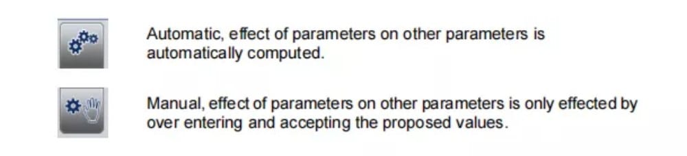
The relation between parameters is visualized with a symbol and a background color.
Automatic mode
1. Introduction
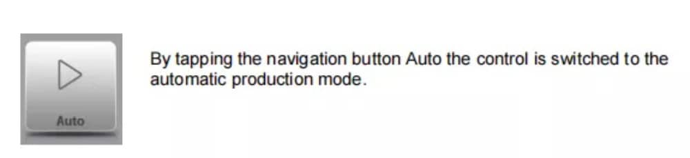
In auto mode with the active program, production can be started. After entering Auto, the Start button can be pressed and production can begin.
The automatic mode executes the program automatically bend by bend after pushing the Start button. When selecting a different product in Products mode, which is in the library and has already been used for production, one can immediately switch to Auto and start production.
Every time after a different bending program is selected you must check your tools and tool positions in your machine. This is also indicated with a ‘check tools’ warning message when you enter the automatic mode.
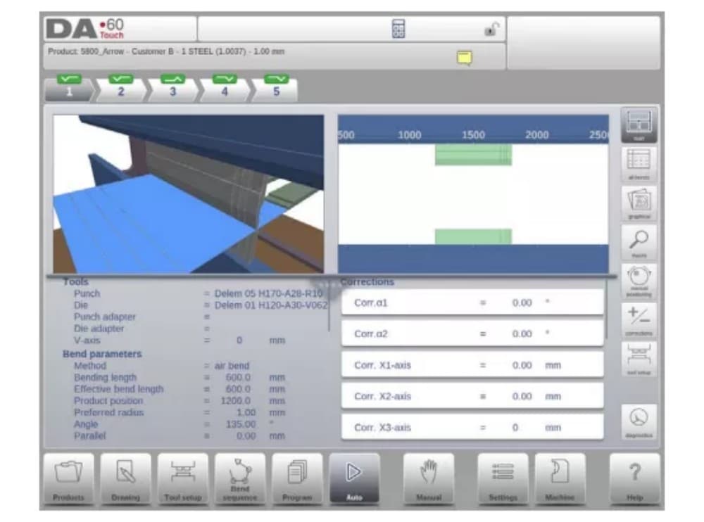
2. View modes
The auto mode screen is offering a diversity of views which, depending on ones production methode, can be chosen. When selecting auto mode for the first time, the main screen will appear. On the right side of the screen the available view modes can be selected.
Following view modes are available:
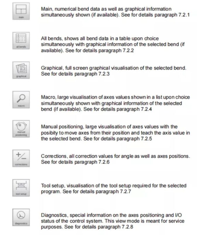
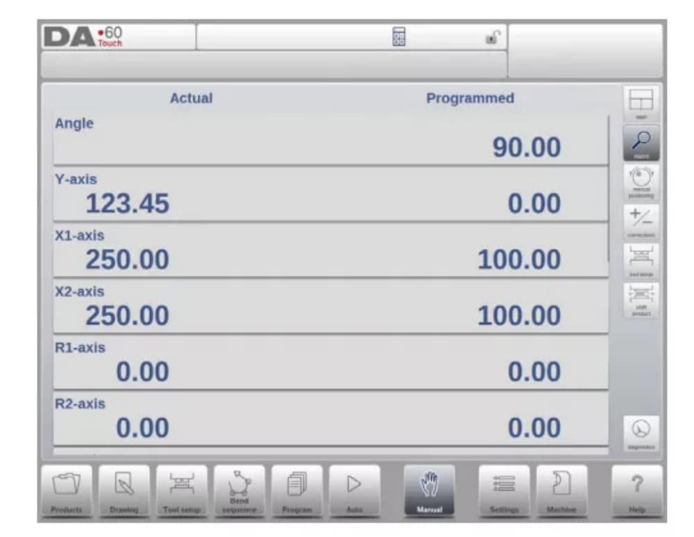
(1) Main
Main view shows the numerical data of the bend along with the corrections. The corrections can be programmed here. The splitter control devides the screen in graphical visualisation and the numerical data. This can be closed if only numerical data is required.
(2) All bends
The all bends view mode shows, with or without the opened graphical pane, a table including all bend data. The bends are shown row wize and the columns display all bend parameters.

(3) Graphical
In graphical view mode a full screen graphical view of the bend process is given.

(4) Macro
With macro view mode, the control switches to a view with only large axes values on the screen. This view can be used when working a little remote from the control, still able to read the axes values.

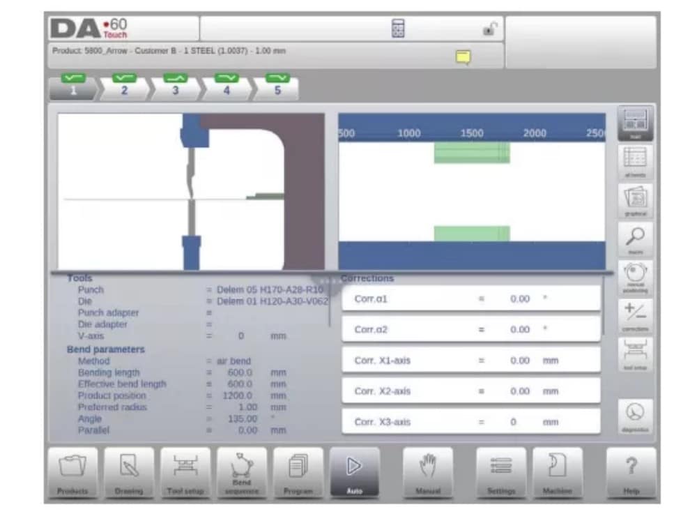
(5) Manual positioning
In manual positioning view mode the axes values are shown at large. Axes can be selected and while selected the position can be controlled by turning the handwheel.
The teach indicator:

When the teach indicator arrow is pressed, standing in between actual value and programmed value, the value is tought to the program step
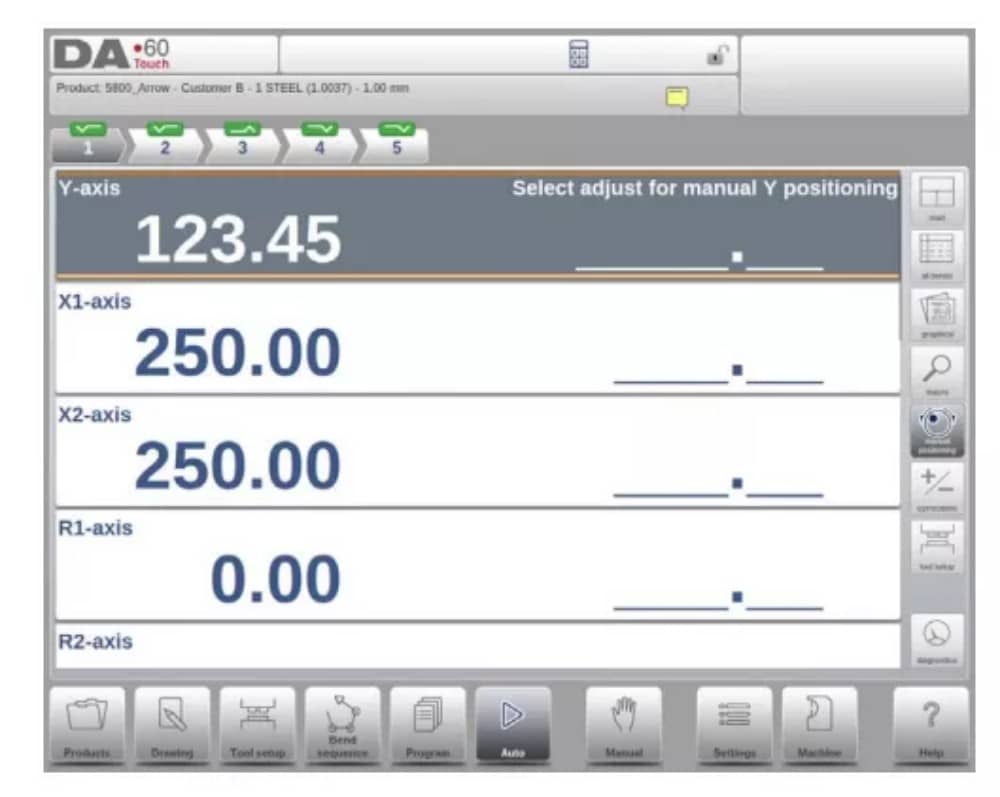
3. Notes
The notes which can be added to a product or program can be viewed in Automatic mode.
With the presence of the notes indicator its indicated that notes are added to this product and by tapping the indicator these will be shown.
Notes can be added generally to a product or program but also to specific bends. Within the notes also PDF documents can have been included. The PDF button will open de document.
4. Bumping correction
In case of a selected bumping bend a general correction for a bumping bend can be entered. This function is only available if a product is loaded that contains a bumping bend.
With Bumping Corr. a new window appears in which the correction can be entered.

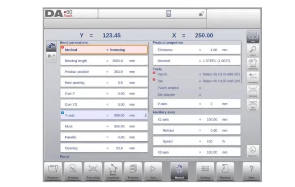
Manual mode
1. Introduction
In manual mode you program the parameters for one bending. This mode is useful for testing, for calibration and for single bends.
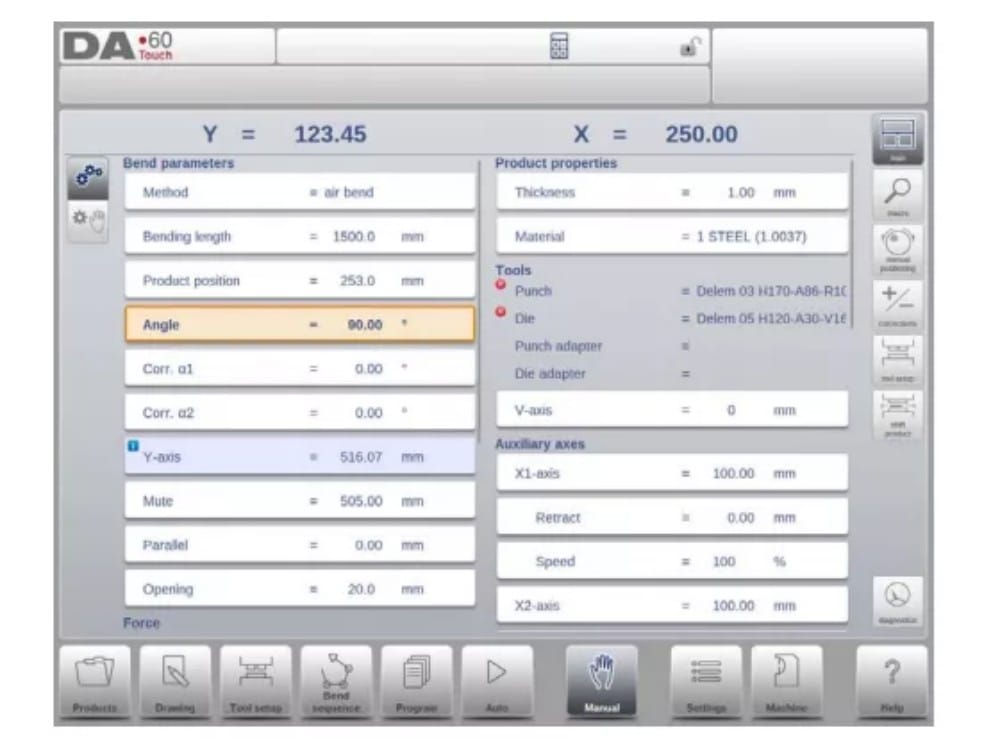
Manual mode is independent from Automatic mode and can be programmed independently of the programs in memory.
2. Programming parameters & Views
Parameters in manual mode can be programmed one by one. The effect of the parameter on other parameters can be computed either automatically or manually. This depends on the selected mode on the left-hand side of the screen. The Auto Computation switch enable to
select between:
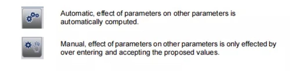
The relation between parameters is visualized with a symbol and a background color.
3.Macro
With Macro the control switches to a new view with only large axes values on the screen. This view can be used when working a little remote from the control, still able to read the axes values.
4. Manual movement of the axes
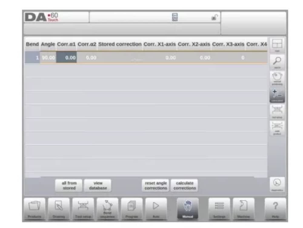
5. Corrections
In this view mode the corrections for the bend programmed in Manual mode are shown. Since this is always a single bend, a single line will be shown.
6. Diagnostics
When tapping Diagnostics, the control switches to a view which shows axes states. In this window, the current state of available axes can be observed. This screen can also be active while the control is started. As such, it can be used to monitor the control behaviour during a bend cycle.

Settings
1. Introduction

The Settings mode of the control, which can be found in the navigation panel, gives access to all kind of settings which influence the programming of new products and programs.
Default values and specific constraints can be set.
The settings are divided across several tabs logically organizing the different subjects. In the following sections the available tabs and detailed settings are discussed.

2. General
Select the required tab and tap the parameter to be changed. When parameters have a numerical or alphanumerical value, the keyboard will appear to enter the desired value. When the setting or parameter can be selected from a list, the list will appear and selection can be
done by tapping. Longer lists allow scrolling vertically to check the available items.
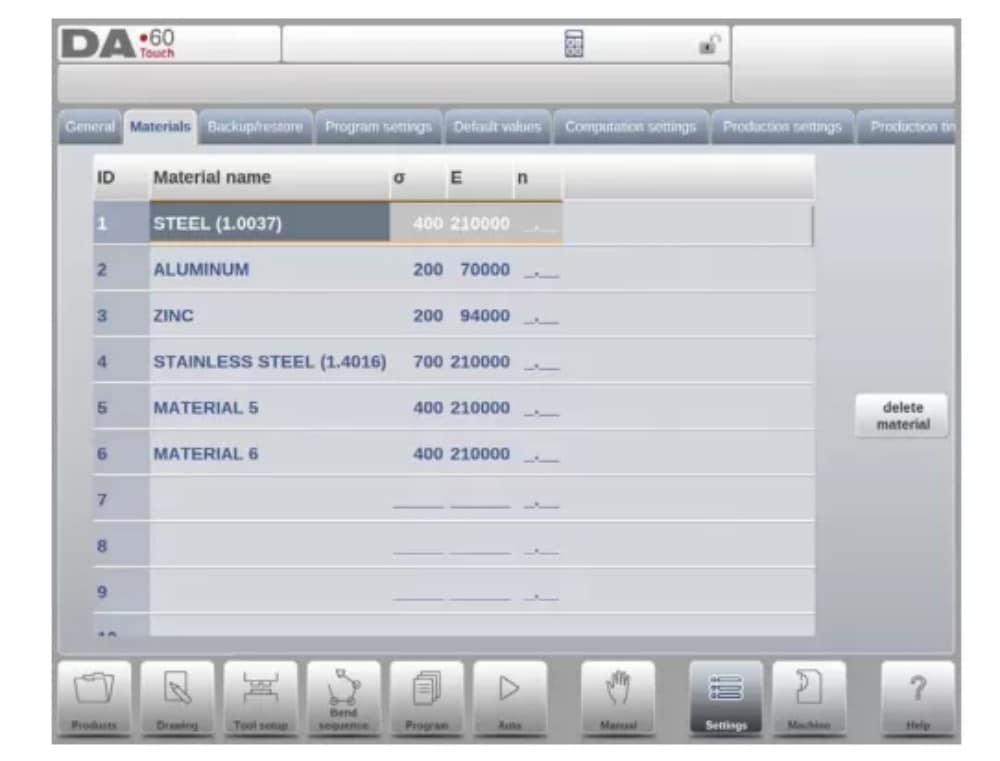
3. Materials
In this tab, materials with their properties can be programmed. Existing materials can be edited, new materials can be added or existing materials deleted. A maximum of 99 materials can be programmed on the control.
4. Backup / restore
This tab offers the possibilities to backup and restore products, tools as well as settings and tables. When products or tools originate from older control models, the DLC-file format products and tools can also be restored using this specific restore function.
For materials a specific backup and restore are available here.
Tools and products can be backupped and restored according to the following procedures. The procedures for saving or reading data are similar for all types of backup media: e.g. network or USB stick.

The actual backup directory consists of a device (USB stick, network) and a directory. The choice of devices depends on which devices have been connected to the control. If necessary, directories can be created and selected. The backup locations for storage of products and tools can be set independently.
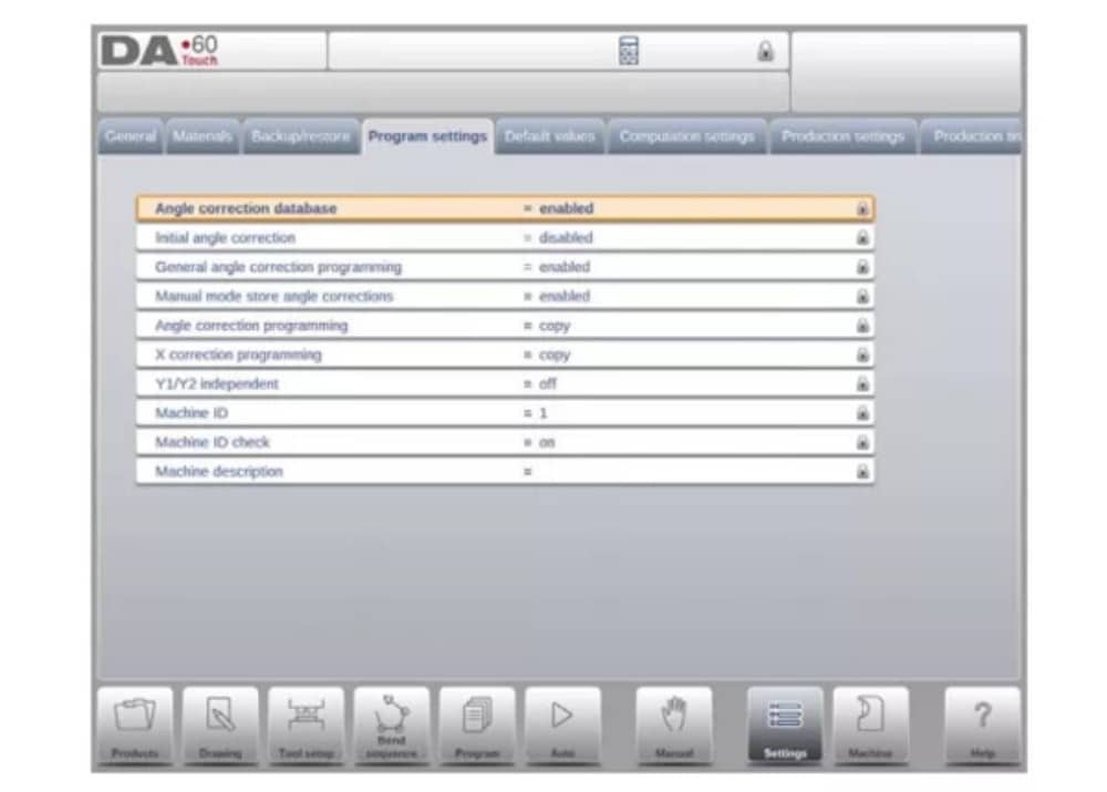
5. Program settings
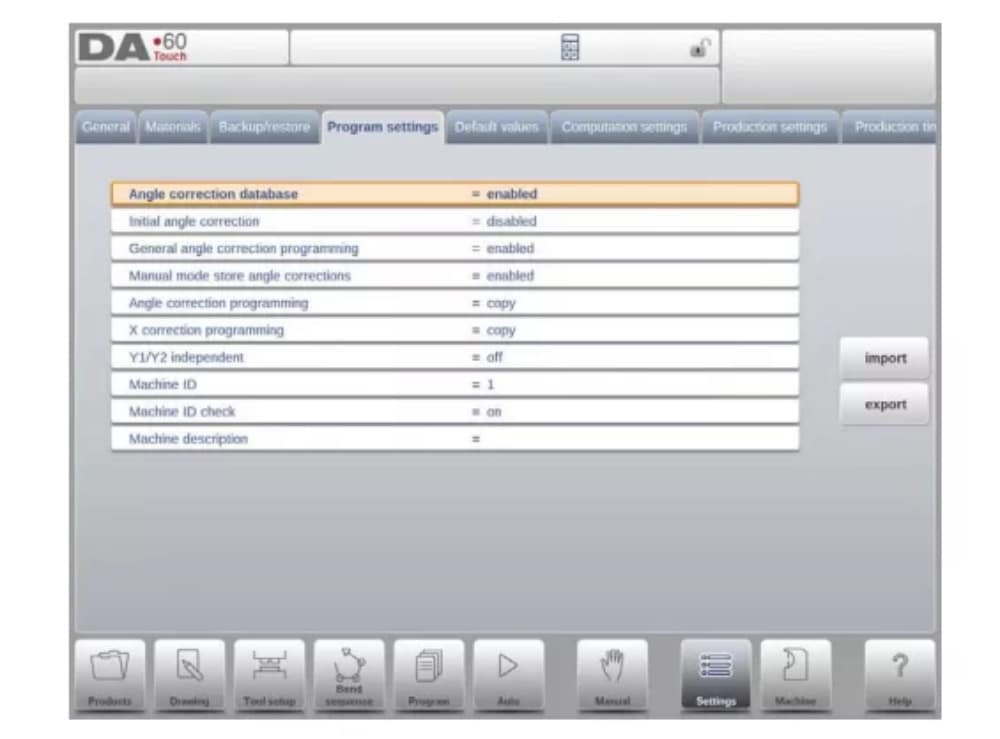
Angle correction database
Parameter to enable the database with angle corrections.
6. Default values
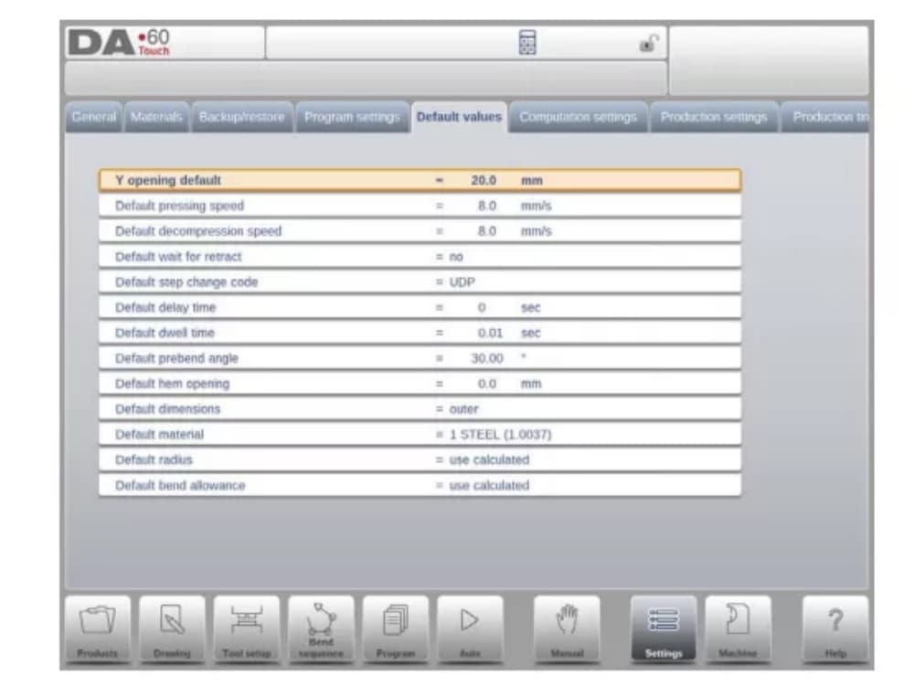
Y opening default
Default Y-axis opening, used as initial value for the parameter ‘opening’ in a new program.
7. Computation settings
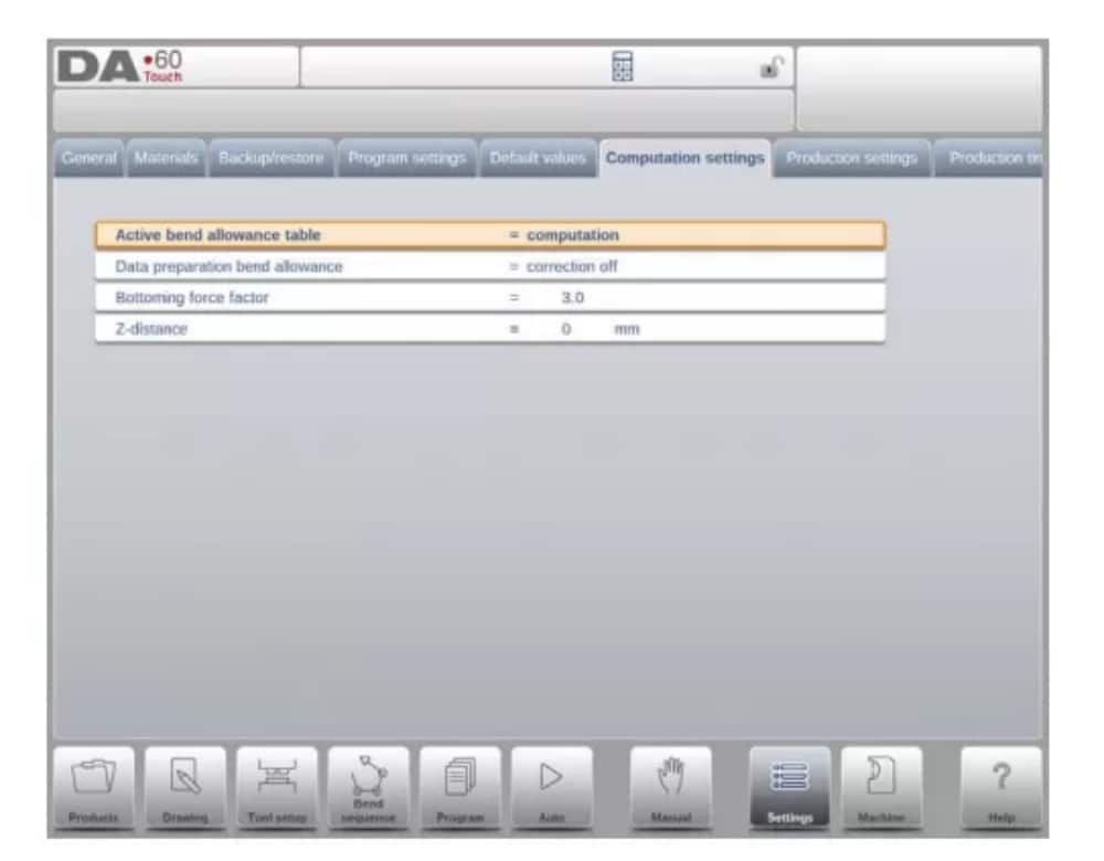
Active bend allowance table
computation => the control will calculate the bend alowancetable => the bend allowance table will be used
Bend-allowance is the correction of the X-axis due to sheet shortening after bending.
With this parameter the method for bend-allowance calculation is chosen. ‘Computation’ means the standard formula of the control is used to calculate the bend-allowance.
‘Table’ means a bend-allowance table with correction values can be used.
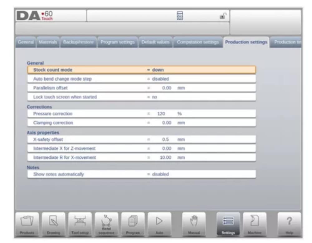
8. Production settings
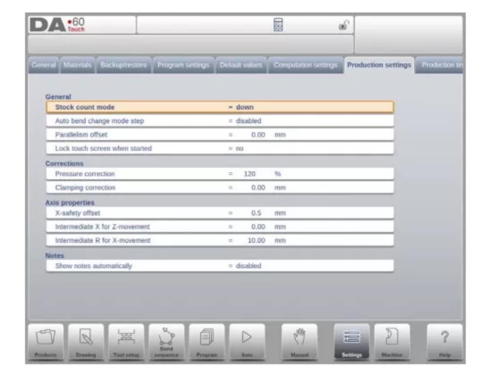
Stock count mode
Setting for the stock counter in production mode, to have the stock counter (product counter) count up or down.
When down counting is selected, the stock counter in production mode is decremented after each product cycle. When the counter has reached zero, the control is stopped. On
the next start action, the stock counting value is reset to its original value.
When up counting is selected, the counter is incremented after each product cycle.
Down counting can be useful if a pre-planned quota must be produced. Up counting could be used to give a report on production progress.
9. Production time calculation
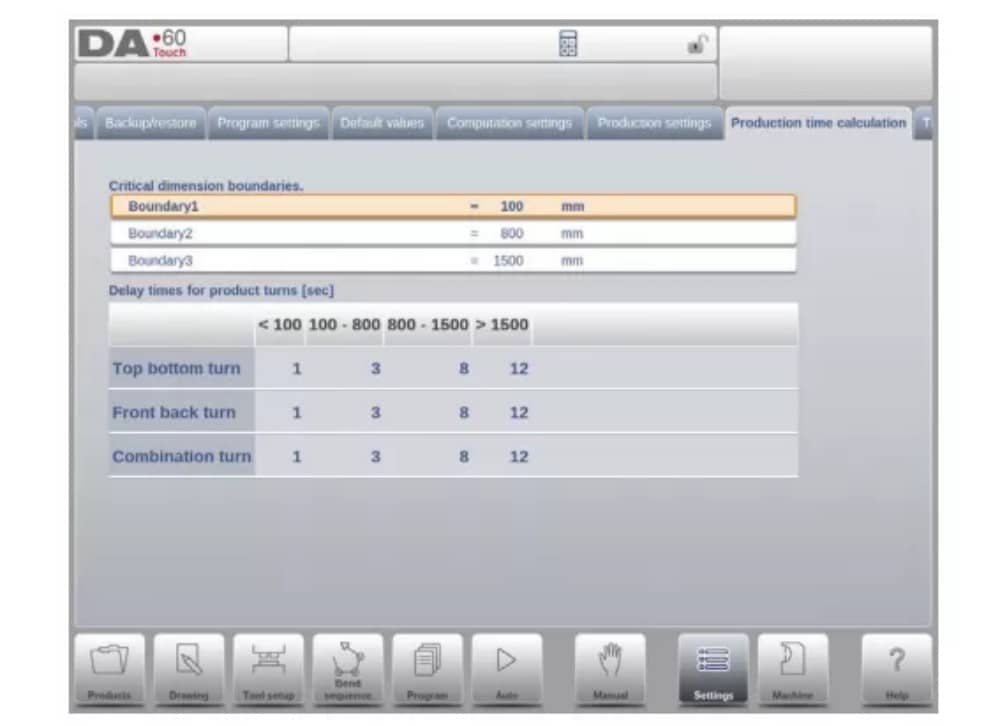
The parameters on this page are used to calculate the production time for a product in the bend sequence computation process. This production time depends on the positioning speed of the axes and the product handling times. The positioning speed is depending on machine settings.
10. Time settings

Display time
Display date and time on the title panel, time only or no time at all.
Machine
1. Introduction
The Machine mode of the control, which can be found in the navigation panel, gives access to the configuration items of the machine and specific machine characteristics which influence generic calculations and machine behaviour.
The settings are divided across several tabs logically organizing the different subjects. In the following sections the available tabs and detailed settings are discussed.
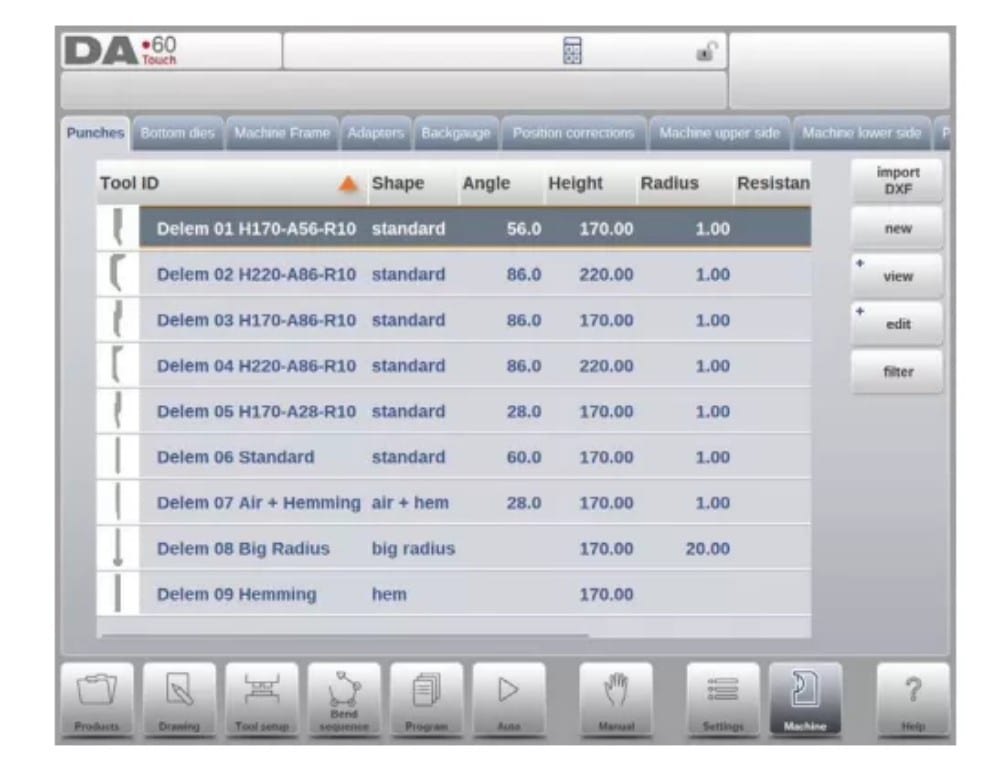
2. Programming of Punches
In this tab, the punches used in the machine can be programmed. New punches can be added; existing punches can be edited, copied, renamed and deleted.
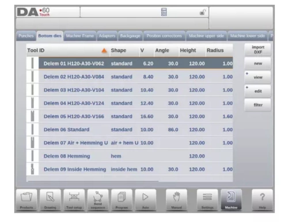
3. Programming of bottom dies
In this tab, the bottom dies used in the machine can be programmed. New dies can be added; existing dies can be edited, copied, renamed and deleted.
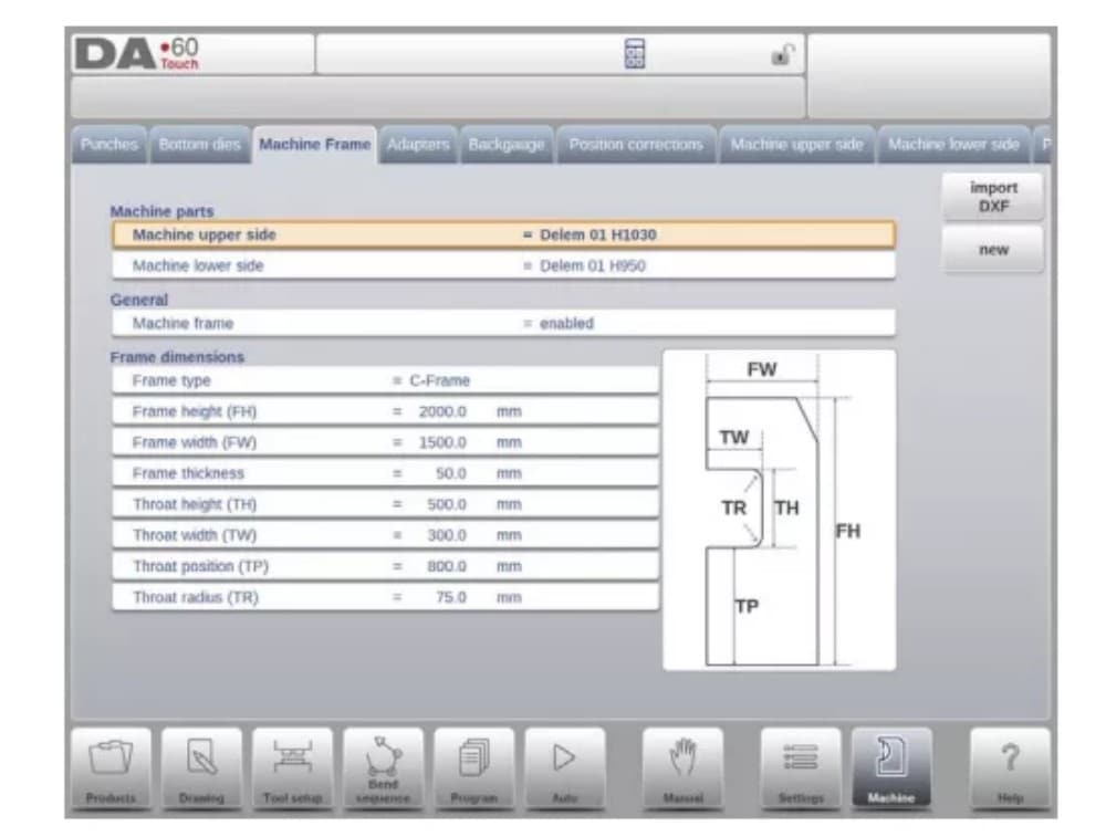
4. Machine frame
On this tab the active machine geometries from upper and lower beam and the side frames, can be selected and set. Also the machine identification can be programmed here.
Next to the Machine Upper Side and Machine Lower Side which are chosen from those available, the Side frame dimensions can be programmed in this page.
The machine shape is shown in the simulation screen during graphical programming and used for the collision detection for work piece against machine.
5. Adapters
On this page the tool adapters can be enabled and programmed.
Upon choice upper adapters as well as lower adapters can be enabled. The default adapter, which will be chosen when an adapter is added to the tool setup, can also be set.
When adding an adapter, first basic parameters need to be given based on a template. In the second stage the adapter details can be drawn like any other punch or die.
6. Backgauge
With the backgauge finger dimensions the R-axis movement and related X-axes movement is taken into account. Also the workpiece / backgauge collision is computed using the dimensions.
7. Position corrections

8. Machine upper side
In this tab the machine geometry for the upper beam, as a profile, can be programmed. This information is used in the collision detection of collisions with product and machine.
When e.g. utilities are added to the machine in special cases, these can be programmed as a special machine shape to enable the collision calculations to take this into account.
In most instances there is only one shape programmed.
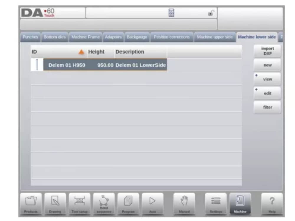
9. Machine lower side
In this tab the machine geometry for the lower side (table), as a profile, can be programmed.
This information is used in the collision detection of collisions with product and machine.
When e.g. utilities are added to the machine in special cases, these can be programmed as a special machine shape to enable the collision calculations to take this into account.
In most instances there is only one shape programmed.
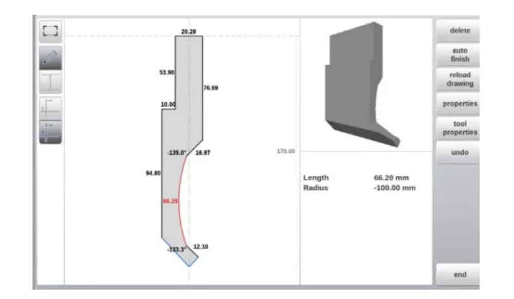
10. Drawing functionality for tools, adapters and machine shapes
In programming punches, dies, adapters and also machine shapes, after the main data the control provides the functionality to freely draw the desired shape in the object. This
functionality makes the objects appear more realistic but most of all enables the control to do an accurate collision prevention.
11. DXF import for tools, adapters and machine parts
Within the tool library, Punches, Bottom dies, Adapters as well as the machine shapes, Machine upper side, Machine lower side and Machine Frame, one can find the optional DXF
import function. This function enables the import of the contour from a DXF file.
Import DXF opens the file browser enabling the selection of the DXF file of the desired shape.

12. Protractor

13. Event logging
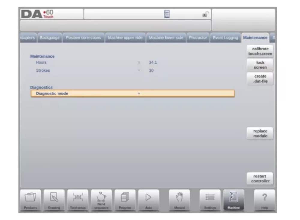
14. Maintenance
On this tab maintenance related functions are located. Next to the machine hour counter and the machine stroke counter also functions to help replace modules and to store diagnostic data can be found here.
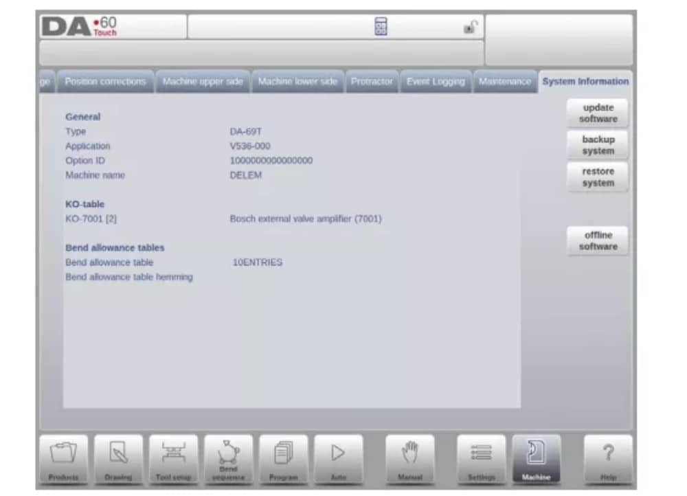
15. System information
On this tab system information can be found. Next to version information on the software also ID’s of the installed modules and version of OEM-specific files can be read.
Next to information also software update functionality is available here.
Profile-T
1. Introduction
(1) General
The Profile-T offline program offers a similar user interface as a DA-Touch line Delem control. The previous chapters, describing the operation and use of the DA-Touch control should be used as a reference for using this offline software. This chapter will focus on a few special functions that are only available in the Profile-T software.
(2) System requirements
To run Profile-T on a computer it should at least be equipped with the following features:
• IBM-compatible PC;
• Minimum Screen resolution of 1024×768
• Windows XP / Windows 7;
• CD-ROM Player (only for CD-ROM distributed systems);
• Free USB port
(3) Profile-T distribution & manuals
Depending on the purchase package the Profile-T software is distributed on a CD-ROM or can be generated at the control.
2. Profile-T operation
(1) Profile-T principle
The next figure shows the start page of Profile-T:
(2) Machine library
It is important that the parameters in Profile-T are the same as in the control on the machine.
In this way the offline generated programs are 100% compatible with the control system. In Profile-T you install several machines in order to use 1 offline programming station for the complete machine range on the production floor.
(3) Print functionality (Profile-T2D and Profile-T3D only)
In Products mode it is possible to generate a print out of the selected product (Profile-T 2D and Profile-T 3D only). When pressing the button ‘print’ the standard Windows printer menu is opened to select the desired printing device and printer settings
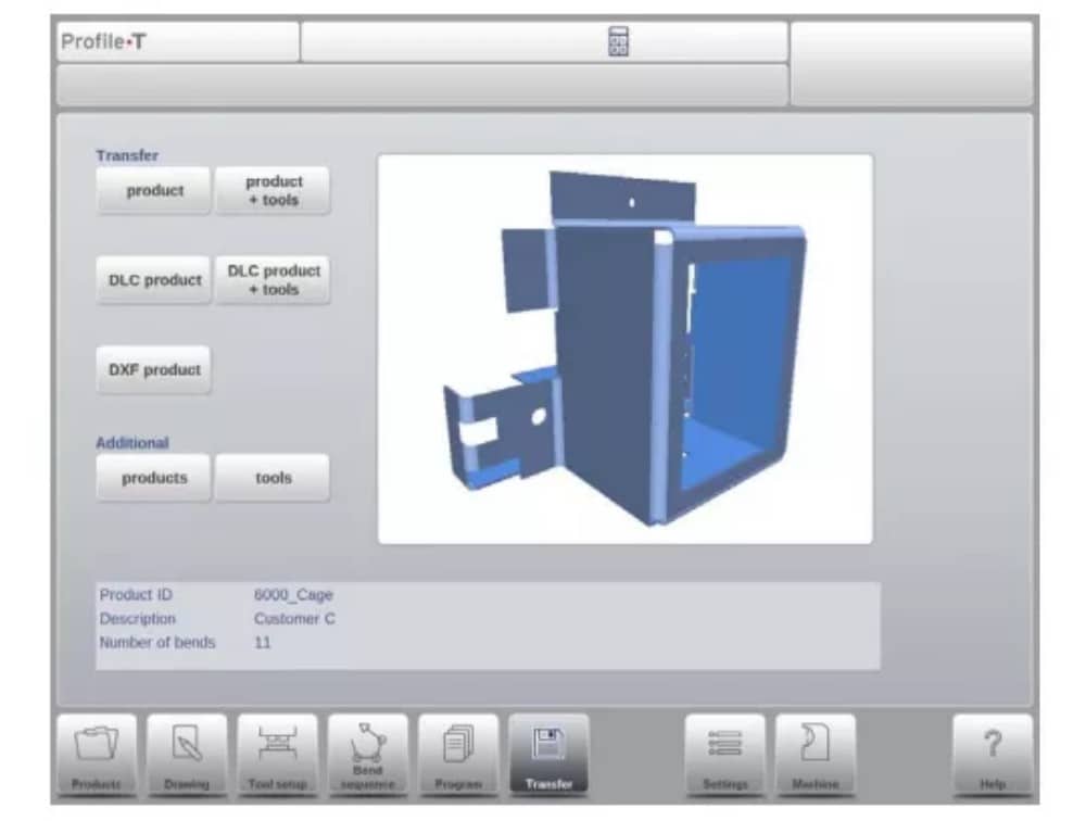
(4) Transfer mode
When the product design and CNC program generation are finished, this data can be transferred in Transfer mode to e.g. a USB memory device.