Views: 220 Author: Site Editor Publish Time: 2017-12-22 Origin: Site


A sheet folding machine that can be operated through hydraulics by two hydraulic cylinders or manually (with the cylinders disengaged) was designed. The design need emanated from the strained national electrical grid system that has recently seen industrialists and households in Zimbabwe experiencing major power cuts. The machine enables manufacturers to schedule heavier jobs during periods when power supply is up and lighter jobs during power cut periods hence run their workshops throughout the daily production shifts. The two hydraulic cylinders can be disengaged from the machine’s folding beam so that manual operation can be done through a manual clamping lever system. The folding force at full capacity is 294.6 KN (29.46 Ton), total bending length of 1.8 m and working height of 1 m. The folding force decreases significantly in manual operating mode to 500 N, considering that on average an operate can manually exert that force. A student version of Simulation X 3.5 was used to simulate the hydraulic operation of the machine.
INTRODUCTION Sheet metal bending and folding accounts for the production of a wide range of consumer durable goods. The demand of goods that fully or at least partly comprise of bent sheet metal parts promises to remain high. Typical products made from sheet metal folding include enclosures, electric boxes, casings for electrical and electronic gadgets, trays, lids, troughs, air ducts, and chimneys. The pape will articulate the design of the components of the folding machine which comprise of the folding beam, the clamping beam, the hydraulic system, selection of a pump to power the hydraulic system, design of the hydraulic cylinder connections such that they can be easily disengaged from hydraulic to manual mode. Currently the bulk of available sheet metal folding machines are operated manually whilst few hydraulic operated ones exist. The operation of hydraulic folding machines is greatly affected by the power cuts hence the need for a machine that operates both on hydraulic and manual mode. Designing a dual operation mode machine gives the manufacturers more flexibility on limited resources as compared to buying two machines with different operating modes so that the other can be shelved when there is no power supply. To deal with this problem, this article focuses on the design of dual-mode sheet metal folding machine that has the ability to be disengaged from hydraulic mode to manual mode in the shortest period of time. With the growth of Small and Medium scale Enterprises (SMEs) worldwide, the folding machine can be used to produce a wide range of products in small factories for local market as well as foreign markets with low power consumption since the operators can choose to switch into the manual mode even during periods when there is power supply.
CLASSIFICATION OF SHEET METAL BENDING PROCESSES
There are various sheet metal processing operations, for instance, laser cutting and bending, punching, deep drawing and redrawing, bending, incremental forming, shearing and blanking, stretch forming, rubber hydroforming, spinning and explosive forming (Groover, 2010). Bending along a straight line is the most common of all sheet forming processes; it can be done in various ways such as forming along the complete bend in a die, or by wiping, folding or flanging in special machines, or sliding the sheet over a radius in a die (Marciniak, 2002). The terms folding and bending are loosely used in the sheet-metal industry and largely interchangeable in common parlance, to be precise, the term ‘folding’ refers to sharp corners with a minimum bend radius and the term ‘bending’ refers to deflections of relatively large corner radii. Folding and bending involve the deformation of material along a straight line in two dimensions only (Timings, 2008).
Bending by Press Brakes
Bending is a metal forming process in which a force is applied to a piece of sheet metal causing bending of it to an angle and forming the desired shape (Manar, 2013). The process is typically performed on a machine called a press brake which can be manually or automatically operated. To bend sheet metal, a bottom tool (die) is mounted on a lower, stationary beam (bed) and a top tool (punch) is mounted on a moving upper beam (ram) (Simons, 2006). The opposite configuration is also possible. Bending produces a V-shape, U-shape, or channel shape along a straight axis in ductile materials, most commonly sheet metal. Commonly used equipment include box and pan brakes, brake presses, and other specialized machine presses. A typical press brake is illustrated in Figure 1.
")
V-die bending can be used in two different ways: for “air bending” or for “bottoming”. In air bending the punch stops a certain distance above the bottom. The die set can be used for bending at any angle larger than 85°. The bottoming die bends the sheet metal at an angle of the die, which may be 90° or any other angle. Both types of V-die bending allow for over bending, which means that the bends under 90° can be produced. Figure 2 shows V-bending die sets.
")
Sheet Metal Folding Machines
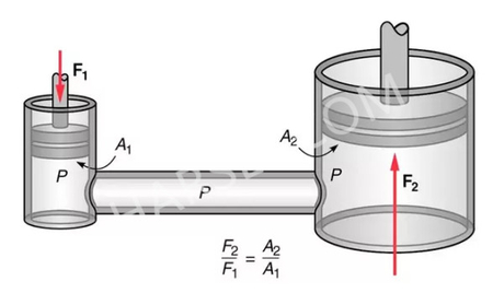
Sheet metal folding process is performed on sheet metal folding machine. The machine consists of a clamping beam that holds down the sheet metal work, and a folding beam that performs the folding operation. The clamping beam consists of a detachable clamping blade and the folding beam of a hard and removable segment, this allows for damaged segments to be replaced. Another feature on the folding machine is a back gauge that allows for highest repeatability of work. Two types of sheet metal folding machines are available, one that is hydraulic powered and one that operates manually. Manual folding machines however have some disadvantages in that they are not conducive to higher production rates, quality or repeatability; however they are suitable for low scheduling light workloads. Hydraulic powered sheet metal folding machines counteract the disadvantages of manually operated sheet metal folding machines, but they have a limitation in that they are affected by power cuts. Hence the design on a folding machine that operates both on hydraulic and manual mode will minimize the impact of power cuts on the production rate and also at the same time improving on quality work through scheduling of light workloads during periods of power cuts and scheduling of other demanding workloads during periods in which electricity is available. Hydraulic Power System Sheet metal working machines can be classified according to energy supply. Five categories can be identified as follows; Mechanical: Where the work force is supplied by some mechanical means such as a cam or lever. Hydraulic: These utilize the pressure of water or other fluid media. Steam: They use pressurized steam. Electromagnetic: Uses electromagnetic force. Hydraulic power system was chosen for the folding machine because of the following advantages over other methods of power transmission (Dawei, 2008):
• Simpler design – In most cases, a few preengineered components will replace complicated mechanical linkages.
• Flexibility – Hydraulic components can be located with considerable flexibility. Pipes and hoses instead of mechanical elements virtually eliminate location problems.
• Smoothness – Hydraulic systems are smooth and quiet in operation. Vibration is kept to a minimum.
• Control – Control of a wide range of speed and forces is easily possible. • Cost – High efficiency with minimum friction loss keeps the cost of a power transmission at a minimum.
• Overload protection – Automatic valves guard the system against a breakdown from overloading. The main disadvantage of a hydraulic system is maintaining the precision parts when they are exposed to bad climates and dirty atmospheres, hence protection against rust, corrosion, dirt, oil deterioration, and other adverse environmental conditions is very important. Disposal of the hydraulic fluid is also a threat to the environment.
DESIGN OF THE FOLDING MACHINE COMPONENTS
Detailed design calculations for sizing the folding machine components are carried out in this section. The initial conditions for basing the design on are given in Table 1.
Maximum Folding Force
The force required to perform folding depends on the strength, thickness, and length of the sheet metal (Groover, 2010). The maximum
")
Clamping Beam Design
The clamping beam exerts a force that holds down the sheet metal onto the folding bed. The hold down force when performing folding operation is 50% the required folding force since it is applied across two ends of the machine. Therefore the clamping force is given by:
Clamping force = 0.5 x folding force
Clamping force = 0.5 x 294.6 kN
Clamping force = 147.3 kN
The clamping beam is designed such that it is welded onto side plates that are connected to a clamping mechanism as shown in Figure 3.
")
The clamping mechanisms are located on both sides of the clamping beam, but the clamping knob is only located on one end. The adjusting screws on the clamping mechanism must resist the clamping force they are exposed to. Operation of the clamping mechanism is illustrated in Figure 4.
The load is shared equally on either side of the clamping mechanism, therefore is equal to half the clamping force that is 73.65 kN. Allowable stress levels to 75% of proof strength are to be used in the clamping mechanism bolts. The selected material for the clamping mechanism according to the Society of Automotive Engineers (SAE), is grade 4 with no head marking and proof strength of 65 ksi.
Then the allowable stress is:
a = 0.75 x proof strength ...(2)
a = 0.75 x 65000 psi
a = 48759
psi The force on each side of the clamping mechanism is 73.65 kN = 16.55
klb Therefore the required tensile area to which the force should act is:
a t Load A ...(3)
2 48750 / 16550 lb in lb At 2
At 0.339 in
Tensile stress area of 0.339 in2 requires a diameter of 7/8 inches, which is equivalent to 22.22 mm. Hence the diameter of the clamping mechanism column should be 22.22 mm with a course thread of 9 threads per inch.
Design of the Folding Beam
Figure 5 shows the front view for the folding beam
")
")
The beam is supported on its two ends and the other force (including its weight) acting on the beam is the maximum required folding force of 294.6 kN acting uniformly across the length of the beam. Figure 6 represents the loading on the beam.
")
Total force acting on the beam = (294.6 + 58.135t) kN
")
Taking moments and resolving forces at determined points along the folding beam and factoring a safety factor of n = 3, and an allowable stress of 350 MPa, t is found to have the following value;
t = 0.015 or t = -0.015
Therefore the thickness of the folding beam is 15 mm.

 English
 Pусский