Views: 97 Author: Site Editor Publish Time: 2017-12-29 Origin: Site


Design of the Hydraulic System Figure 7 shows the design of the hydraulic circuit system of the metal folding machine.
")
The folding force is evenly distributed between the two hydraulic cylinders. Load on each hydraulic cylinder 147.3 kN The axial load on each hydraulic cylinder can be determined using the angle of inclination of the cylinders. The angle of inclination, is determined using Figure 8.
")
")
")
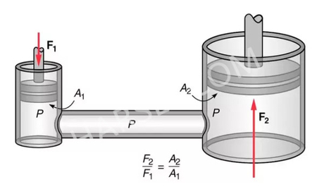
For the hydraulic system an operating pressure of 150 bars is selected. The effective piston area, Aeff, is calculated below using Equation 5.
")
Using preferred cylinder sizes and piston diameters, we determine that the appropriate piston diameter, d, is 56 mm.
The annulus area, Aa , is calculated using Equation 7.
")
The stroke of the hydraulic cylinders is determined with reference to Figure 10.
")
")
Using the stroke obtained above the velocity, ve , of the hydraulic cylinder during extension of a period of 4 seconds can be determined as follows:
")
Hydraulic Pump Sizing
The hydraulic pump supplies the pressurized fluid for cylinder actuation. A vane pump is to be used to power up the hydraulic system. The following calculations will be useful in sizing the desired pumping unit. Taking a volumetric efficiency, nv , of 90% and speed rating of 1200 rpm, we can obtain the theoretical pump delivery.
")
From the calculations above a hydraulic vane pump with a rating of 1200 rpm, a displacement of 4.29×10⁻⁵ m3 and a flow capacity of 51.4 litres/min (13.58 GPM) is selected. Reservoir Design
The most suitable hydraulic tank volume is two to three times the pump capacity. Selecting a factor of 2.5, the capacity of the hydraulic reservoir is calculated as follows:
Reservoir volume = 2.5 x pump capacity
Reservoir volume = 2.5 x 51.4 litres
Reservoir volume = 128.5 litres = 0.1285 m3
A reservoir should be high and narrow rather than shallow and broad. Therefore, a rectangular prism shaped reservoir with a length, l, of 0.8 m and width, w, of 0.4 m is chosen. The height, h, of the reservoir is calculated as follows:
")
The height tank will have to be greater than 0.401 m because there must be a clearance volume above the oil, therefore the new height of the tank chosen will be 0.45 m.
Cylinder Connections
The attachment of the hydraulic cylinders to the folding beam has to be detachable to enable
")
switching of the machine from hydraulic to manual mode. Figure 11 shows the details of the cylinder connections on the machine. At the base fitting a clevis mounting is used that provides a single pivot mounting point on the cylinder. At the end fitting a bearing eye head is used to mount the cylinder onto the folding beam. The cylinder will be detached on the end fitting to disengage manual mode. A detachable connection using an M24 bolt with a shank length of 60mm will be used to connect the cylinder onto the folding beam.
HYDRAULIC SYSTEM SIMULATION RESULTS
To simulate the operation of the hydraulic cylinder, a package called ‘Simulation X 3.5’ was used. The simulation give a mathematical imitation of the operation of each hydraulic cylinder over the period from fully closed to fully open which takes 4 seconds. Figure 12 represents the simulation results of the piston stroke over the complete cycle time; a maximum stroke of 590 mm is attained.
")
Figure 13 displays the flow rate from the pump to the directional control valve, from the calculations a flow rate of 51.4 l/min was obtained.
")
Figure 14 shows the pressure supplied by the pump of 150 bars during the 4 seconds
")
Figure 15 shows the acceleration on the load, in the first split seconds there are high accelerations due to shock as the load is starting is move. The acceleration then
")
COMPLETE FOLDING MACHINE MODEL
A complete model of the designed dual operating mode sheet folding machine is shown in Appendix A. The model shows the location of the clamping mechanism (on one end of the machine) and a protractor gauge is located on the side frame for angle measurement during the bending operation. CONCLUSION
The article has demonstrated an engineering procedure for design and validation by means of simulation, of a dual operating mode sheet metal folding machine. A non-commercial hydraulic simulation package (Simulation X 3.5) was used for simulation of the hydraulic system for the machine. A constant operating pressure of 150 bars will be maintained during machine operation whilst the folding bar shows a rapid acceleration, within a fraction of a second, towards the specimen sheet metal before it reaches a steady approach during the actual bending operation. This action prevents whipping of the specimen sheet metal and also gives good quality bending of sheet metal parts. A full scale version of the sheet metal folding machine can be manufactured to benefit the small and medium enterprises since the machine can be scheduled to operate manually and through hydraulic actuation.
")

 English
 Pусский