Views: 2413 Author: Site Editor Publish Time: 2024-04-18 Origin: Site


Sheet metal bending machines are the backbone of modern metalworking industries, enabling the transformation of flat metal sheets into complex shapes and structures. From automotive parts to household appliances, the versatility of these machines is unmatched. But how exactly do they work their magic? Let's delve into the inner workings of sheet metal bending machines and uncover the mechanics behind their precision and efficiency.
Sheet metal bending is the manufacturing process by which most enclosures, electrical boxes, brackets and components are formed through the use of a machine known as a CNC press brake. (Panel Bending machines can also be used, although their operation is outside the scope of this feature.)

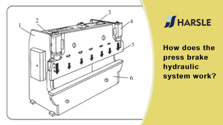
Sheet metal is bent when it is forced between two tools by the press brake: an upper tool (known as a punch) and a bottom tool (known as a die). The press brake controls the movement of either the punch or the die and provides the press force using hydraulic rams or electrical servo motors. The bend angle is predominantly determined by the depth of penetration of the punch within the die.
The maximum force provided by the press brake determines the maximum bend length for a combination of thickness of sheet metal, bend radius and bend angle. The force required to bend sheet metal increases with bend length, external bend angle and sheet metal thickness, and it decreases with increasing bend radius. Hydram’s press brakes have varying capabilities and maximum bend length of 4 metres and a maximum force of 250 tonnes are available. The table below illustrates some typical examples for 90 degree bends:
| Mild steel thickness | Bend length | Inner | Reguired Force |
| 1.5mm | 3000mm | 2mm | 45tonnes |
| 3mm | 1500mm | 4mm | 51tonnes |
| 6mm | 1000mm | 8mm | 48tonnes |
| 9mm | 500mm | 13mm | 34tonnes |
Components vary in complexity, from parts with a single bend, through to parts with multiple bends with multiple flange lengths. Modern pressbrakes are equipped with adjustable backstops, driven by servo motors, against which the components are offered by hand or robotic manipulator. The closer the backstop to the tooling, the shorter the resulting flange is and vice versa.
On complex parts, the backstops adjust after each bend to the corresponding distance required for the next bend. The movement of the backstops and the press brake tooling is synchronised by a CNC controller. CNC programs can be generated online on the machine user interface or by an offline programming (or CADCAM) software package.
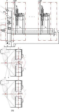
A variety of press brake tools is available to suit different sheet metal bending tasks. The characteristics of the upper and lower tools are varied according to the requirements of the sheet metal component. A number of bending examples are illustrated below:
Thicker metal is generally processed with a larger bending radius, and this can be achieved by increasing the top tool radius and the distance across the die opening – or V-width.

Components that require a sharp bend angle require “over bending” tooling. Both the top and bottom tools in this case have a more acute angle.

Components that have more than one bend often require special top tooling to provide clearance for existing flanges. Without this clearance the component would collide with the tool before the subsequent bend operation was complete. This type of tooling is often referred to as gooseneck.

To provide clearance in extreme cases, the top tool can be suspended from the press brake beam using modified clamps. These extended clamps provide far greater clearance for large flanges, so long as the metal bending machine has sufficient stroke length to accommodate the overall tool height.
When designing sheet metal components with folds or bends it is necessary to create a flat pattern or blank development of the part. This blank is then laser cut or CNC punched before arriving at the press brake for folding. In creating the blank, it is important that the design takes into account the bend radius formed by the press brake tooling. The bend radius has the effect of decreasing the developed blank size. The larger the radius, the smaller the blank, as shown in the example below:

The bend radius varies with the material thickness and the tooling used for bending the material. It is therefore essential that the designer is aware what tooling will be used to bend the material and have a good appreciation what affect this has on the bend radius. Likewise, to ensure accuracy of the bent component, the metal bending machine operator needs to know what radius the part has been designed with so that the correct tooling choice is made.
1. Setup: The operator selects the appropriate tooling and enters bending parameters into the CNC control system.
2. Material Preparation: The metal sheet is loaded onto the machine and aligned with the back gauge.
3. Bending: The hydraulic cylinders apply force to the punch, pressing it into the die and bending the metal sheet to the desired angle.
4. Springback Compensation: Some materials exhibit springback, meaning they return to their original shape after bending. Advanced CNC systems can compensate for springback to achieve precise bend angles.
5. Unloading: Once the bending process is complete, the finished part is removed from the machine for further processing or assembly.

 English
 Pусский