Images (1)

Aug. 21, 1934. w. FERRIS El AL 1,970,999
HYDRAULIC PRESS Filed May 31. 1930 gwue'nfo'o WALTER FEHFHS. GEUHGE H. FUBIAN.
Patented Aug. 21, 1934 UNITED STATES PATENT OFFICE HYDRAULIC PRESS Application May 31, 1930, Serial No. 457,8888 Claim.
This invention relates to hydraulic presses.
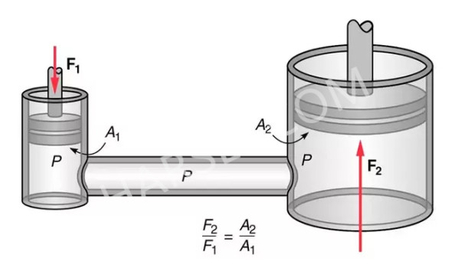
The press to which the invention applies in particular has a ram cylinder connected to a source of pressure liquid, a ram arranged in the cylinder, and means for controlling the delivery of liquid to the cylinder. The liquid acts first upon a limited ram area and advances the ram at high speed and then acts upon a greater ram area and advances the ram at a slower rate of speed but with the ability to exert a greater force than it was capable of when the liquid acted upon the limited ram area.
An object of the invention is to provide a press which is capable of operating at high speed.
Another object is to reduce the volume of liquid which is ordinarily required to be moved during the operation of power presses.
Another object is to provide a press which is sturdy and compact.
A hydraulic riveting machine embodying the invention is illustrated in the accompanying drawing, in which the views are as follows:
Fig. 1 is a side view, partly in section, showing the operating valve in position to retract the ram, and the ram fully retracted.
Fig. 2 is a central vertical section showing the ram advanced.
Fig. 3 is a central longitudinal section showing the operating valve in position to advance the ram.
Fig. 4 is a sectional plan view taken on the line 4-4 of Fig. 1.
Fig. 5 is a schematic drawing showing a different arrangement of ram cylinders.
The riveting machine has a frame 1, a ram cylinder 2 carried by the frame 1 in alinement with a bolster 3 which is shown integral with the frame 1, a die block 4 arranged upon the bolster 3 and supporting a die 5, and a ram 6 arranged in the bore 7 of the cylinder 2 and provided with a die 8 to cooperate with the die 5 in driving a rivet 9 in a piece of work 10.
The ram is provided at its upper end with piston rings 11 to prevent the passage of liquid from one side to the other thereof and the lower part of the ram extends through a cylinder head 12 which closes the lower end of the cylinder 2.
The upper end of the cylinder 2 communicates with an intensifying cylinder 13 which may be formed integral and in alinement therewith,as shown in Fig. 1, or formed separately as shown in Fi 5.
Figs. 1 to 4 The intensifying cylinder 13 contains a secondary or intensifying ram 14 which is pro- ,vided at its upper end with piston rings 15 to prevent the passage of liquid from one side to the other thereof. The lower part 16 of the intensifying ram 14 is reduced in diameter, fitted into the bore 7 and provided with piston rings 17 to prevent the passage of liquid from one side to the other thereof.
The intensifying ram 14 has a bore 18, which extends through the reduced part 16 thereof, and a counterbore 19 which communicates with the bore 18 and has an annular valve seat 20 fitted in the upper end thereof.
The valve seat 20 is adapted to be engaged by a valve 21 which is urged toward the seat 20 by a helical compression spring 22 arranged between the valve 21 and the bottom of the counterbore 19.
The valve 21 is held in alinement with the seat 20 by an angular valve guide 23 which is attached to the valve and abuts the upper head 24 of the cylinder 2 when the ram 14 is in its uppermost position to hold the valve 21 out of engagement with its seat 20 against the action of the spring 22.
The rams 6 and 14 are reciprocated in the cylinder 2 by liquid supplied from a pump 25 which is arranged upon a bracket 26 carried by the frame 1. A pump which may be employed is illustrated and described in Patent No. 1,578,233, issued March 23, 1926 to Walter Ferris.
The delivery of liquid to the cylinder 2 and the discharge of liquid therefrom is controlled by a valve 27 which is arranged upon the side of the frame 1 and has its plunger 28 connected by a rod 29 to a treadle 30 which is pivoted in a bracket 31 and provided with a spring 32 for holding the valve plunger 28 in the position shown in Fig. 1.
The operating valve 27 is connected to the pump 25 by a delivery pipe 33, which has one end connected to the deliveryoutlet of the pump 25 and its other end in communication with an annular port 34 formed in the wall of the valve cylinder, and by return pipes 35 and 36 which connect the ends of the valve cylinder to the inlet of the pump 25.
The valve 27 is connected to the top of the cylinder 13 by a pipe 37, which has its lower end in communication with an annular port 38 formed in the wall of the valve cylinder and I Ti n'the -upper head 24, and to the bottom of the per end connected to the cylinder 13 below the large part of the ram 14 and its lower end connected to the pipe 40 by a free-return resistance valve 43 which comprises a resistance valve 44 and .a checlc valve 45 connected inparallel.
When the rams 6 and 14 are in the positions shown in Fig. 1 and the treadle 30 is operated to move the valve plunger 28 into the position shown in Fig. 3, liquid is delivered by the pump 25 through the pipe 33 and the port 34 into the valve 27, then through the port 38, the pipe 37 and the port 39 into the top of the cylinder 13.
The resistance valve 44 and check valve 45 retain the liquid in the bottom of the cylinder 13 so that the intensifying ram 14 is held in its uppermost position and the valve 21 is heldout of engagement with the valve seat 20 by its guide 23.
The liquid delivered into the top of the cylinder 13 may thus pass through the intensifying ram 14 and force the ram 6 downwardly at a rapid rate until the die 8 engages the rivet 9 and exerts a predetermined force thereon; the liquid in the bottom of the bore 7 being returned to the pump 25 through the pipe 40, the port 41, the valve 27 and the pipe 35.
The resistance oflered by the rivet 9 to the downward movement of the die 8 causes the hydraulic pressure in the. cylinder 2 to rise until it overcomes the resistance of the resistance valve 44 which then opens and allows the liquid in the lower part of the cylinder 13 to be returned to the pump 25 through the pipe 42, the resistance valve 44, the pipe 40, the port 41, the cylinder of the valve 27, and the pipe 35.
When the resistance valve 44 opens, the liquid delivered to the upper end of. the cylinder 13 forces the intensifying ram downward until the valve guide 23 moves out of engagement with the cylinder head 24 and allows the valve spring 22 to urge the valve 21 against its seat 20 as shown in Fig. 2. The liquid in the counterbore 19, in the bore 18, and in the upper part of the bore '7 is thus trapped between the head of the ram 6 and the valve 21.
The ram 6, the intensifying ram 14, and the entrapped liquid new function as a single ram which is moved downward as a unit by the high pressure liquid acting upon the upper end of the intensifying ram 14. As the ram 14 has a much greater cross-sectional area than the ram 6, the force exerted by the die 8 is correspondingly increased and the rivet 9 is driven in the work 10.
When the rivet is driven, the operator releases the treadle 30 and the spring 32 returns the valve plunger 28 to the position shown in Fig. 1.
The liquid delivered by the pump 25 to the valve 2'7 through the pipe 33 now passes into the bottom of'the bore 7 through the pipe 40 and into thecounterbore 13 through the check valve 45 and the pipe 42 to raise the rams 6 and 14. The liquid in the cylinder 2 above the rams 6 and 14 is returned to the pump 25 through the pipe 37, the valve 27 and the pipe 36. The ram and the valves are now in the position shown in Fig. 1 and the machine is in condition to start a second operation.
Fig. 5 The arrangement shown in this figure is the same as that shown in Fig. 1, except that theram cylinders are arranged at an angle to each other and connected by a bent pipe 46, and like parts have been indicated by like reference numerals.
The reduced part 16 of the ram 14 extends into the reduced part 4'7 of the cylinder 13 which corresponds to that part of the cylinder of Fig. 1 above the ram 6.
The bore of the reduced part 47 may besmaller than the bore of the cylinder 2 and thereby provide a greater increase in pressure than in the arrangement shown in Fig. 1.
The invention herein set forth is susceptible of various modifications and adaptations without departing from the scope thereof as hereafter claimed.
The invention is hereby claimed as follows:
1. A hydraulic press, comprising a frame, a ram cylinder and an intensifying cylinder carried by said frame and connected to each other, a main ram arranged in said ram cylinder, an intensifying ram arranged in said intensifying cylinder and having a passageway extending longitudinally therethrough, a self-closing valve arranged in said passageway to close the same and having a guide normally in engagement with the head of said intensifying cylinder to hold said valve open, a control valve connected to the upper end of said intensifying cylinder and to the lower end of both of said cylinders, a check valve and a resistance valve connected in parallel between the lower end of said intensifying cylinder and said control valve, a source of liquid under pressure, a delivery pipe for delivering liquid from said source to said valve, return pipes for delivering .liquid from said valve to said source, means for operating said valve to connect the lower ends of said cylinders to said return pipe and to direct liquid into the top of said cylinder and through said passageway to advance said main ram at a rapid rate until it meets sufflcient resistance to cause a rise of pressure in said cylinder sufllcient to open said resistance valve and thereby allow said intensifying ram to move downwardly and said self-closing valve to close andtrap the liquid between said rams, whereby the liquid delivered to said cylinder acts upon the upper end of said intensifying ram and increases the force exerted by said main ram, and means for reversing said control valve to connect the top of said cylinder to said return pipe and to direct liquid into the lower end of said ram cylinder and through said check valve into the lower end of said intensifying cylinder to retract said rams and to hold the same in retracted position.
2. A hydraulic press, comprising a ram cylinder, a main ram fitted in said cylinder, an intensifying cylinder having a greater cross-sectional area than said ram cylinder and com-' thereby retard the advance of said intensifying ram to enable said motive liquid. to advance ed resistance is encountered thereby and then advance said intensifying ram, means for trapping liquid between said rams whereby the total force exerted by said motive liquid upon the large area of said intensifying ram is transmitted to said main ram through said entrapped liquid, and means for retracting both of said rams.
3. A hydraulic press, comprising a ram cylinder, a main ram fitted in said cylinder, an intensifying cylinder having a borev communicating with said ram cylinder and a counterbore of greater cross-sectional area than said ram cylinder, an intensifying ram fitted in said bore and said counterbore, means for delivering pressure liquid to one end of each of said cylinders, a resistance valve for resisting the discharge of liquid from the inner end of said counterbore to thereby retard the advance of said intensifying ram to enable said pressure liquid to advance said main ram at high speed until it meets a predetermined resistance and to then advance said intensifying ram, means for trapping the liquid between said rams, and means for directing pressure liquid to the other endsof said cylinders to retract said rams.
4. A hydraulic press, comprising a ram cylinder, a main ram fitted in said cylinder, an intensifying cylinder having a bore communicating with said ram cylinder and a counterbore of greater cross-sectional are than said ram cylinder, an intensifying ram fitted in said bore and said counterbore and having a passageway extending longitudinally therethrough, means for delivering pressure liquid to one end of each of said cylinders, a resistance valve for resisting the discharge of liquid from the imier end of said counterbore to thereby retard the advance of said intensifying ram to enable said pressure liquid to advance said main ram at high speed until it meets a predetermined resistance and to then advance said intensifying ram, a valve arranged within said passageway for trapping the liquid between said rams, and means for directing pressure liquid to the other ends of said cylinders to retract said rams.
5. A hydraulic press, comprising a ram cylinder having a bore-and a counterbore, a main ram fitted in said bore, an intensifying ram fitted in said bore and said counterbore, a source of motive liquid, means for delivering motive liquid from said source to said bore and said counterbore to advance said rams, a resistance valve for the exhaust of liquid from said counterbore to thereby resist the advance of said intensifying ram whereby said liquid will first advance said main ram until it meets a predetermined resistance and will then advance said intensifying ram, means operated in response to the movement of said intensifying ram for entrapping liquid between said rams whereby the force exerted by said motive liquid upon said intensifying ram is transmitted to said main ram through said entrapped liquid and means for retracting both of said rams.
6. A hydraulic press, comprising a ram cylinder having a bore and a counterbore, a main ram fitted in said bore, an intensifying ram fitted in said bore and said u ounterbore, means for delivering pressure liquid to said bore and said counterbore to advance said mm, a resistill I I ee auso quid 7. A hydraulic press, comprising a ram cylinder having a bore and a counterbore, a main ram fitted in said bore, an intensifying ram fitted in said bore and said counterbore and having a passageway extending there through for the passage of liquid from said counterbore to said bore, means for delivering pressure liquid to said counterbore to advance said rams, a resistance valve for resisting the exhaust of liquid from said counterbore to thereby resist the advance of said intensifying ram'whereby said liquid will first advance said main ram until it meets a predetermined resistance and will then advance said intensifying ram, a valve controlling said passageway and operated in response to the movement of said intensifying ram to trap liquid between said rams whereby the force exerted by said pressure liquid upon said intensifying ram is transmitted to said main ram through said entrapped liquid, and means for delivering pressure liquid to said cylinder to retract said rams.
8. In a hydraulic press, a press cylinder and a plunger, a pump adjustable to vary its output for delivering fluid under pressure to said cylinder, said pump being provided with means for automatically maintaining the fluid on the pressure side thereof at a predetermined maximum, a reversing valve under manual control for selectively placing the suction or pressure side of said pump in communication with said press cylinder, an intensifier including a piston head and plunger provided with an axial bore, a connection between said cylinder and theaxial bore of said intensifier plunger, a connection between said pump and one end of the piston head of said intensifier, said last two named connections and said axial bore providing a continuous passage from said pump to said cylinder at the beginning of the operation, a connection between the other end of said piston head of the intensifier and the suction side of said pump, a back pressure valve in said last named connection, an expansion tank connected with said pump and to the connection between said back pressure valve and said pump, said back pressure valve including a one-Way ball valve and a spring loaded valve operative to place said intensifier in communication with said expansion tank and the suction side of said pump when the pressure in said intensifier exceeds a predetermined amount during the working stroke of said press to permit movement of the piston of the intensifier to materially increase the pressure on the press plunger for the pressing operation.
WALTER FERRIS. GEORGE H. FOBIAN.

 English
 Pусский