Views: 1148 Author: Site Editor Publish Time: 2024-04-07 Origin: Site


Sheet metal bending mainly uses bending machines to bend the sheet metal in a straight line, which is suitable for processing narrow and long linear parts. The bending operation of the bending machine is completed by the upper and lower bending dies fixed on the sliding block and the table.

According to the different bending equipment used, the bending method is also different. There are three commonly used methods as follows.
In free bending, the sheet metal is typically clamped or held in place at one end while the other end is manipulated to achieve the desired bend angle. This process allows for a wide range of bend angles and shapes to be formed, depending on the skill of the operator and the characteristics of the material being bent.
The working principle of free bending is shown in figure (a) below. The V-shaped lower die 1 is fixed on the worktable of the press, and the upper die 2 reciprocates up and down with the slider of the press. Place the sheet material 3 on the lower mold, and the upper mold downwardly bends the sheet material and controls the depth of the upper mold into the lower mold to obtain workpieces with different bending angles.
The advantages are: A series of different bending angles can be obtained with a set of simple V-shaped molds.
The disadvantages are: the vertical deformation of the press, the difference in the performance of the plate, and the small changes will cause obvious changes in the bending angle, so it is required to accurately control the bottom dead center of the slider movement, and the elastic deformation of the press and the rebound of the workpiece itself Wait for compensation.
Forced bending is commonly used in industrial manufacturing processes for its ability to produce accurate and repeatable bends in sheet metal components. It is suitable for high-volume production and allows for complex shapes to be formed with tight tolerances.
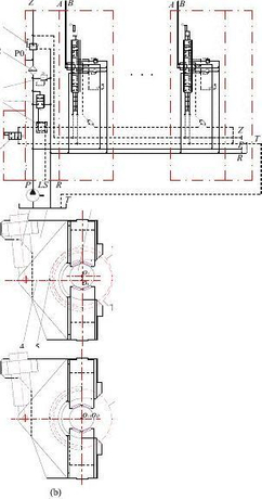
The working principle of forced bending is shown in figure (b) below. Forced bending is in the final stage of bending. The upper die 2 presses sheet 3 against the V-shaped groove of the lower die 1 so that it has a correction function. The rebound of the workpiece is limited to a small range. But a set of V-shaped molds can only obtain a certain bending angle, so all the angles of the workpiece must be equal, otherwise, the mold needs to be replaced.
The working principle of three-point bending is shown in the following figure (c). In addition to the two places on the lower die 1 that are in contact with the sheet material 3, the upper plane of the bottom movable block 4 is also in contact with the sheet material, so it is called "three-point bending.
The slider is equipped with a hydraulic cushion, so the movement accuracy and deformation of the press and the performance change of the sheet will not affect the bending angle of the workpiece. It only depends on the depth H and width W of the lower die groove, and With the nature of forced bending, it is possible to obtain a workpiece with a small spring back and high precision. Obviously, by adjusting and controlling the upper and lower positions of the movable block, different bending angles of the workpiece can also be obtained on the mold set.
On modern bending machines, forced bending methods are rarely used, and free bending and three-point bending are commonly used. For example, at present, the most widely used hydraulic sheet metal bending machine, its machine tool movement adopts hydraulic step-less pressure regulation and adopts the working mode of free bending. When working, the lifting and lowering of the slider and the adjustment of the upper and lower positions are carried out accurately by hydraulic cylinders adjust. The stroke adjustment of the slide block and the adjustment of the back gauge positioning are mostly used for electric quick adjustment and manual fine adjustment, and are mostly equipped with a digital display device, and can be equipped with a numerical control system to realize the automatic control of the back gauge and the stroke of the slide block. The retaining accuracy of this kind of numerical control mechanism is generally up to ±0.1mm or more, which can be used for continuous and rapid bending of workpieces with multiple different bending angles, which greatly improves production efficiency.

Common bending methods
The bending dies installed on the bending machine can be divided into two types: general dies and special dies. The figure below shows the shape of the end face of the general bending die.

Universal bending die
The upper mold is generally V-shaped. There are two types: straight arm type and curved arm type. The angle of the upper mold with smaller rounded corners is made 15°, and the fillet radius of the upper mold is made into a set of several fixed sizes to facilitate Replace according to the needs of the workpiece.
The lower die is generally made of several fixed notches suitable for the bending parts of the machine tool on the four faces. Generally, V-shaped and rectangular, both obtuse and acute-angled parts can be bent. The length of the lower die is generally the same as that of the work. The tabletops are equal or slightly longer. The height of the upper and lower dies of the bending die is determined according to the closing height of the machine tool, and the bending angle is greater than 18° when the bending die is used.
When using a universal bending die to bend parts on a bending machine, the width B of the lower die slot should not be less than twice the sum of the bending fillet radius R of the part and the material thickness t, plus a gap of 2mm, that is: B>2(t+R)+2. In this way, the blank will not be blocked or produce indentation and scratches during bending. At the same time, to reduce the bending force, a wider notch should be used for hard materials, and a smaller notch should be used for softer materials. A large notch will bend the straight side into an arc.
When bending a blank with a bent edge, the distance from the center of the lower die slot to its edge should not be greater than the length of the straight side of the bent part. The dimension d in figure (a) below must be smaller than dimension C, otherwise, the blank cannot be placed. When bending the semi-finished product into a hook shape and then bending it, a lower die with an escape groove should be used, as shown in figure (b) below.

Bending with crimped parts
The choice of the upper mold also needs to be carried out according to the requirements of the shape and size of the part. The fillet radius of the working end of the upper mold should be slightly smaller than the bending radius of the part. Generally, the straight arm type is used. When the straight arm type upper mold is blocked, it should be replaced with a curved arm type upper mold.
When using general-purpose molds to bend complex parts with multiple corners, according to the number of corners, the bending radius, and the shape of the parts, the baffle must be adjusted multiple times and the upper and lower molds must be replaced. The order of first and second bending is very important. It not only affects the structure of the mold and the number of bending parts, but sometimes determines whether the parts can be manufactured. The general principle is: when bending, the bending should be performed from the outside to the inside, that is, first The outer angle of the bend, the inner angle of the back bend, the previous bend must consider the reliable positioning of the subsequent bend, and the subsequent bend cannot affect the shape of the previous bend.
Special bending molds must be used for bending parts with large production volume or special shapes of parts. The special bending die can be used in conjunction with the general bending die, or the parts can be bent separately. The picture below shows the special bending die used on the bending machine.
The following figures (a)~(c) are the process of using a special bending die to bend into a round tube in multiple steps. The special die shown in the following figure (d) can realize multiple bending parts at one time, and the production efficiency is very high. And the mold shown in the following figure (e) is the special bending mold used in the last process, because the opening of the part is very small, the general bending mold can only complete the bending of the first few processes.

No matter which kind of bending die is used, before operating the bending machine, the following preparations should be made: first, remove the obstacles on the work surface and the machine tool, and lubricate the machine; secondly, check whether all parts of the machine work normally, If the problem is found, repair it in time, especially check whether the pedal is flexible. If it is found to be connected to the car, it is never allowed to use it.
Generally speaking, the bending machine can be operated according to the following process.
1.Lower the slider of the bending machine to the lowest position and adjust the lowest point of the slider so that the closed height of the slider to the working table is 20-50mm larger than the total height of the upper and lower bending dies.
2.Raise the slider and install the upper and lower molds. The general procedure is to first put the lower mold on the worktable, then lower the slide block and then install the upper mold. When installing the upper mold, keep both ends parallel, move from one end of the slide block to the fixed mold groove and push it inward. The middle position of the sliding block makes the machine force balanced and fixed firmly with screws.
To prevent the upper mold from falling and hurting the lower mold or hurting your hands during installation, you can put a few wooden blocks on the lower mold, preferably a few wooden sticks of the same diameter, which can not only prevent the above accidents but also use wooden sticks to support When the upper mold is pushed inward because it is parallel, it is labor-saving and safe.
3.Start the adjustment mechanism of the slider to make the upper mold enter the lower mold slot, and move the lower mold so that the centerline of the upper mold apex is aligned with the centerline of the lower mold slot, and the lower mold is fixed.
At present, on some bending machines, taking into account the convenience of installation and debugging of the upper and lower molds, the lower mold is also designed as a lower mold pad and a lower mold split, which are connected in the form of a U-shaped notch, although the subsequent mold replacement is more Convenient, but the first installation and debugging should still be carried out according to the above steps.
4.Raise the slider and adjust the stopper mechanism installed on the back of the worktable according to the bending size, so that the upper die mouth and the bending line of the sheet material coincide. If the equipment has a digital display or numerical control function, it can be adjusted by electric power, and its positioning size It can be directly: display or programmed control. If the equipment does not have an electric adjustment function, the positioning size of the blank can be adjusted manually when working. The structure of the stopper mechanism is shown in the figure below. Among them: bracket 5 is fixed in the T-shaped groove on the side of the workbench with a fastening handle 6 and can be adjusted up and down. Slider 2 can move back and forth along bracket 5 to adapt to the required position. If the adjustment amount is small, the baffle plate 1 can also be adjusted back and forth by the fine adjustment nut 4 and fastened with handle 3.

1-Baffle plate 2- Slider 3.6- Fasten the handle 4-Fine adjustment nut 5-Bracket 7-Die 8-Blank
When working, generally mark the measured dimension A value, its value is:
A=L+ B/2+C
A: The distance from the side of the lower die to the baffle, mm;
B- Width of lower die slot, mm;
C1 The distance from the side of the lower die to the edge of the slot of the lower die, mm;
L-The distance from the bending line to the edge of the blank, mm.
The A value needs to be tested and then adjusted appropriately. The bending size can only be determined after the first inspection, self-inspection, and special inspection are passed.
5.Adjust the bending angle as required. The bending angle only needs to adjust the depth of the upper mold into the lower mold, and it is easy to meet the requirements. Generally, after several bending trials with waste materials, the bending work can be determined.
For parts that need to be bent multiple times, the order of bending is generally: from outside to inside; proceed. That is, first bend the corners of the two ends, and then bend the corners of the middle part, and the previous bending must consider the reliable positioning of the subsequent bending, and the subsequent bending does not affect the formed part of the previous bending.

Sequence of bending
Processing methods of common bending parts
The universal bending machine is used with some special dies for bending, which is not only quick to put into production but also very economical. Therefore, it is widely used in production.
Figure 1 shows a common bending part and its bending die formed by folding edges and corners.
Figure 2 shows a common folding and forming bending piece and its bending die.
Figure 3 shows a common bending piece formed by a lock and its bending die.
Figure 4 shows a common bending piece and its bending die.

Figure 1 Bending parts and bending molds formed by folding edges and corners

Figure 2 Folding and forming bending parts and bending die

Figure 3 Bending part and bending die for lock forming

Figure 4 Bending part and bending die for bending angle forming
Sheet metal bending is a versatile and essential process in modern manufacturing, construction, and fabrication industries. By mastering the principles and techniques of sheet metal bending outlined in this guide, you'll be equipped to tackle a wide range of bending projects with confidence and precision. Whether you're a beginner or an experienced professional, this ultimate guide serves as a valuable resource for expanding your understanding of sheet metal bending and achieving optimal results in your projects.

 English
 Pусский