


ESA S929 Numeric Program is one of the most commonly used programming methods for creating bending jobs quickly and efficiently. By entering numerical values such as material dimensions, bend angles, tooling information, and backgauge positions, operators can generate accurate bending programs without using graphical programming functions. If you want to learn how to create, edit, save, and manage a numeric program on the ESA S929 controller, this guide will walk you through the complete setup process step by step. Whether you are a beginner learning CNC programming or an experienced operator looking to improve productivity, understanding ESA S929 Numeric Program configuration can help you achieve more consistent bending results and faster job preparation.
How to Create a New ESA S929 Numeric Program
The ESA S929 Numeric Program function allows operators to create bending programs by entering numerical values directly into the controller. This programming method is ideal for standard bending operations because it provides a fast and efficient way to generate production-ready programs without using graphical simulation tools.
To create a new ESA S929 Numeric Program, open the Editor page and press the New Program icon.

The controller will automatically open the program setup window where all bending data can be entered.
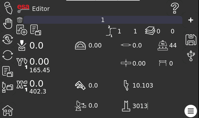
The left side of the screen displays the current machine axis positions, while the central area contains the program parameters and bending sequence information.
Understanding the Main ESA S929 Numeric Program Parameters
When a new program is created, several default parameters are automatically loaded from the most recently used program. These values can be modified according to the current production requirements.
General Program Information
Before entering bending data, review the following parameters:
- عدد الانحناءات
- Material width
- سمك المادة
- مقاومة المواد
- Punch selection
- Die selection
- طريقة القياس
The measurement parameter supports different calculation methods:

- 0 = External measurements (default)
- 1 = Neutral fiber measurements
- 2 = Internal measurements
Selecting the correct measurement method ensures accurate bend calculations throughout the program.
Material and Tool Data
The controller automatically loads the previously used punch and die information. If different tooling is required, select the appropriate punch and die before continuing with program creation.
Correct tooling selection is essential because all bend calculations depend on the tool geometry stored in the controller database.
How to Configure Bend Data in ESA S929 Numeric Program
Each tab at the top of the Editor page represents an individual bend. Operators can switch between bends and enter different parameters for each step.
Setting the Bend Angle
The bend angle is one of the primary parameters in an ESA S929 Numeric Program.

Enter the required bending angle for each step according to the production drawing. The controller uses this value together with the selected tooling and material data to calculate the required machine positions.
Setting the Bend Length
Enter the bend length for the selected bend step.
This value helps the controller determine the required bending force and optimize the machine settings during execution.
Understanding BDC Calculation
The BDC (Bottom Dead Center) value is calculated automatically by the ESA S929 controller using technological formulas.

In most applications, operators do not need to manually calculate this value because the controller generates it automatically based on the entered program data.
Configuring Backgauge Position
The X1 position defines the backgauge location for the selected bend.

Accurate X1 positioning is critical because it determines part dimensions and directly affects bending accuracy.
Additional X1 correction values can be entered when fine adjustments are required during production.

How to Access Advanced Machining Parameters
For additional programming functions, swipe downward on the Editor page to open the Secondary Editor Page.
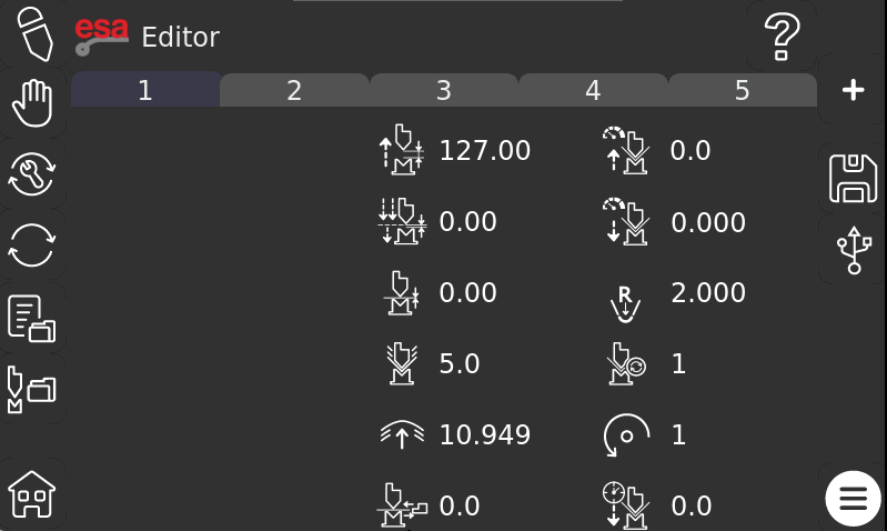
This page contains advanced machining parameters used to optimize bending performance.
مركز الموت العلوي (TDC)
The TDC parameter defines the upper stop position of the ram.

Adjusting this value can help optimize cycle time and machine movement efficiency.
Mute Point
The mute point defines the position where certain machine safety functions change operating status.

This parameter is generally configured according to machine requirements and production conditions.
نقطة الضغط
The pinch point controls the transition point before the bending operation begins.

Correct configuration helps ensure smooth machine operation.
Force Settings
The force parameter determines the amount of pressure applied during the bending cycle.

The required force depends on:
- سمك المادة
- قوة المواد
- طول الانحناء
- فتح القالب
Proper force settings help achieve consistent bending results while avoiding unnecessary machine stress.
Crowning Force
The crowning force parameter compensates for machine deflection during long bending operations.

This adjustment improves angle consistency across the entire bending length.
Additional Parameters in ESA S929 Numeric Program
The Secondary Editor Page also provides access to several advanced production settings.
Change Step Time
This parameter controls the transition timing between bending steps.

Optimizing step changes can improve production efficiency during multi-bend operations.
Matching Function
The matching parameter controls synchronization-related functions within the bending process.

It is typically adjusted according to specific application requirements.
Speed Settings
The speed parameter allows operators to define machine movement speeds during the bending cycle.

Appropriate speed settings help balance productivity and bending accuracy.
Internal Radius
The internal radius parameter represents the expected inside bend radius after forming.

This value may be automatically calculated or manually adjusted depending on the application.
Bend Repetition
The repetition parameter defines the number of repeated bending cycles required for the selected operation.

Piece Rotation
Piece rotation indicates the workpiece orientation between bending steps.

Proper rotation settings help operators follow the correct bending sequence.
Bend Time
The bend time parameter controls the duration of specific bending operations.

It may be adjusted to optimize production quality and machine performance.
How to Use Function Settings in ESA S929 Numeric Program
The Function button provides access to additional bending options.

When the function menu is opened, operators can activate or deactivate specific functions for each bend.
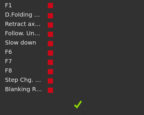
Enabling Bend Functions
To enable a function:
- Open the Function menu.
- Select the desired function.
- Tap the corresponding indicator until it changes status.
- Confirm the selection.
These functions provide additional flexibility for special bending applications.
How to Add Additional Bends
Complex parts often require multiple bending steps.
Creating a New Bend
Press the “+” button located at the top of the Editor page.
The controller will automatically create a new bend step after the currently selected bend.
Editing Multiple Bend Steps
Each bend can have independent settings for:
- زاوية
- Backgauge position
- التصحيحات
- سرعة
- قوة
- الأدوات
This allows operators to create complete multi-step bending programs within a single ESA S929 Numeric Program.
How to Insert a Bend Between Existing Steps
Sometimes additional bends must be inserted into an existing sequence.
Step 1: Select the Reference Bend
Choose the bend located after the desired insertion point.
Step 2: Open the Menu
Press the Menu button.

Step 3: Insert the Bend
Select the “Insert Step” function.

The new bend will be inserted before the currently selected bend, allowing the existing sequence to remain organized.
How to Delete a Bend
If a bend is no longer required, it can be removed from the program.
Select the bend and press the Delete Bend icon.

The selected bend will immediately be removed from the bending sequence.
Deleting unnecessary bends helps keep programs clean and easier to manage.
How to Save an ESA S929 Numeric Program
After all programming data has been entered, the program should be saved.
Saving the Program
Press the Save icon.

The controller will open a naming window where the program name can be entered using the touchscreen keyboard.
After entering the program name, confirm the operation to store the ESA S929 Numeric Program in the controller memory.
How to Use Save As in ESA S929 Numeric Program
The Save As function allows operators to create alternative versions of an existing program.
Creating Program Variants
Open the Menu and select “Save As”.

Enter a new program name and confirm the operation.
This feature is particularly useful when:
- Testing different bend corrections
- Creating production variants
- Maintaining backup versions
- Producing similar parts with minor modifications
Using Save As prevents accidental modification of the original program while allowing flexibility during production development.
الأسئلة الشائعة
Which parameters should I configure in an ESA S929 Numeric Program?
A complete ESA S929 Numeric Program typically includes material width, material thickness, material resistance, measurement mode, punch selection, die selection, bend angle, bend length, and X1 backgauge position. Additional machining parameters can also be configured on the Secondary Editor Page.
Does the ESA S929 Numeric Program calculate BDC automatically?
Yes. The ESA S929 controller automatically calculates the Bottom Dead Center (BDC) using built-in technological formulas based on the programmed material properties and tooling data. In most cases, manual calculation is not required.
خاتمة
Creating an accurate ESA S929 Numeric Program is an important step in achieving efficient and reliable press brake production. By understanding how to configure material properties, tooling information, bend parameters, advanced machining settings, and program management functions, operators can significantly reduce setup time while maintaining consistent bending quality.
In addition to entering correct numerical data, regularly reviewing program parameters, organizing program versions, and using backup features such as Save As can help prevent programming mistakes and improve production flexibility. Taking advantage of the controller’s built-in calculation and editing functions also makes daily operation more efficient.
If you need additional assistance with ESA S929 Numeric Program configuration, press brake programming, or ESA controller operation, feel free to contact the HARSLE technical support team. You can also browse more HARSLE documentation and tutorials to learn advanced programming techniques and maximize your machine’s performance.


