Views: 2658 Author: Site Editor Publish Time: 2024-04-25 Origin: Site


This Paper represents the work implemented in designing, fabricating and operating a model of a cheap hydraulic deep drawing machine (DDM), which is currently utilized in the manufacturing processes lab in the Industrial Engineering Department (IED) at An-Najah National University. The machine is being used in conducting different experiments related to the deep drawing process.
As known, deep drawing is a sheet-metal working process in which a punch draws a blank sheet into a die cavity to form cup-shaped or box-like parts [1].
This work was carried out in three stages; the first was the design stage, in which all design calculations of the DDM elements were completed based on the specifications of the product (cup) to be drawn. The second was construction stage, in which the DDM elements were fabricated and assembled at the engineering workshops of the university. The last was the operation and experimentation stage, in which the DDM was tested by conducting different experiments.
In conclusion, the experience gained in designing and constructing a mechanical lab equipment was found to be successful in terms of obtaining practical results that agree with those available in literature, saving money relative to the cost of a similar purchased equipment, as well as enhancing students’ abilities in understanding the deep drawing process in particular and machine elements design concepts in general.
Keywords: Deep Drawing, Machine Element Design, Dei Design, Machine assembly and Fabrication, Experimental Investigation of Draw Force and Draw Stroke
Deep drawing is a sheet- metal working process used to form cup- shaped or box –shaped parts by using a punch that draws a blank into a die cavity. This process is carried out by placing a blank sheet of certain size over the opening of the die and pressing this blank into the die cavity with a punch, as shown in Figure 1, [1]. Typical products made by this process are beverage cans, bathtubs, containers of different sizes and shapes, sinks, and automobile panels.

In this paper, the basic drawing operation is studied, which is the drawing of a cup-shaped part with parameters as shown in Figure 1, in this basic operation a circular blank sheet of a diameter Db and a thickness t, is placed over the die opening of a die having a corner radius Rd. Then the blank is held by a blank holder (hold-down ring) with certain force. After that a punch of a diameter Dp and a corner radius of Rp is used to punch the blank sheet into the die cavity, thus forming the cup-shaped part.
Moreover, the punch moves at a certain velocity V and applies a certain down ward force F to achieve the deformation of the metal, while the blank holder applies holding force Fh to prevent blank
wrinkling.
Actually, this paper presents the design and fabrication of a cheap Deep Drawing Machine “DDM” that produces pre-identified cup-shaped product, the DDM is now mounted and being used for experimentation in the Manufacturing Processes Lab in the IE department at An-Najah University, the paper presents the detailed design of the DDM main elements including the punch and the die, and the fabrication & assembly of the DDM, it also presents the operation and testing of the DDM through conducting experiments on drawing force versus drawing stroke and compare the results with published data.

This section discusses some general concepts of the deep drawing process including the drawing measures, drawing force and holding force
One of the most important measures of deep drawing operation is the limiting drawing ratio LDR. Limiting drawing ratio is defined as the maximum ratio of blank sheet diameter to punch diameter that can be drawn under ideal conditions in one stroke without failure [2].

The force in the punch required to produce a cup is the summation of the ideal deformation force, the frictional forces, and the force required to produce ironing. Figure 2 shows the relation between the draw force and the draw stroke [2].


The holding force h F plays an important role in the deep drawing. As a rough approximation, the holding pressure can be set at value equals 0.015 of the yield strength of the sheet metal [1].
Thus by multiplying the holding pressure by the portion of the starting area of the blank which is to be held by the blank holder, we can estimate the holding force ( h F ) as [1].

A double-action mechanical press is generally used for deep drawing, hydraulic presses are also used. The double action press controls the punch and blank holder independently and forms the part at a constant speed.
Since blank holder force controls the flow of the sheet metal within the die, now presses have been designed with variable blank- holder force. In these presses the blank holder force is varied with punch stroke.
The most important factor in the die design is the corner radius ( d R ) of the die. This radius must have an optimum value since the material is pulled over it. The value for the optimum radius of the die depends upon the print requirement and the type of the material being drawn. Obviously, the smaller the die radius, the grater the force needed to draw the cup. The radius of the die may be between four to eight times the thicknesses of the blank [3].That is
![]()
Practically, it is recommended to start with d R equal 4t and increase it if necessary.
Similarly, the punch nose radius ( p R ) is important since it shapes the radius of the bottom of produced cup. If p R is too small, the bottom radius of the cup may tear out. It may be necessary to make the radius larger than needed, and reduce its size in subsequent drawing operations. As a start, a 4t radius –to- blank thickness may be used. [3].
The DDM was designed to produce cup-shaped parts in a single stroke, as stated earlier, the purpose of designing the DDM is to provide the manufacturing processes lab at An-Najah University with an apparatus that can demonstrate the deep drawing process and also be used by students to perform some basic experiments related to the deep drawing process. Actually, in order to design a proper DDM, it is necessary first to determine the product (the cup) specifications, drawing force and holding force.
The product of the required DDM is chosen to be a simple cup having a certain inner diameter (d) and depth (h) and to be produced using a sheet metal of thickness (t).
The dimensions of the cup must be selected such that the deep drawing operation is feasible to produce the cup in single stroke; to measure the feasibility of the operation, the LDR, thickness-todiameter ratio (t/D) and the reduction (Re) percentage must satisfy the feasibility conditions mentioned in section2 of this paper. To do so, It was decided that the thickness of the sheet metal to be used in producing the cup is t 1 32in. 0.8mm, hence -based on the recommendations stated in section 2-

The cup is to be produced from Yellow Brass C 26800 (65% Cu, 35%Zn) with UTS 322MPa,S 98MPa. y Using equation (5) with Dp = 50 mm; one can calculate the drawing force to produce the cup as F = 36.4 KN. Similarly, from equation (6) Fh = 14 KN. So the total drawing force (Fd) to be applied by the DDM equals the summation of F and Fh, that is Fd = 50.4 KN. For design purposes of DDM elements; the Fd shall be multiplied by a load factor equals to 1.6.
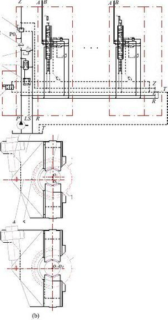
This section presents the design of selected main elements of the deep drawing machine (DDM). Figure (4) shows a section of the DDM, its elements and the associated legend. Figure (5) is its photo.

Once the cup specifications have been determined as previously explained, one can determine the specifications of the die and the punch being used to produce that cup.
Namely, the punch must have an outer diameter equal to the inner diameter of the cup, i.e. of 50 mm. It also has to be high enough to produce the required depth (20 mm) of the cup. Hence, the punch was designed to have an outer diameter of 50mm, punch radius ( p R ) of 3.2 mm, and a height of 80mm.
Die and punch are the mating parts in this process; therefore, the internal diameter of the die will be the same as of punch outer diameter plus the compensation of the clearance between them. Figure (6) illustrates the dimensions of the die.
The upper support plate, as its name indicates, is used to support the DDM by holding the hydraulic cylinder of the machine. Therefore, the design of this plate must be based on the maximum force provided by the hydraulic unit which equals 1.6 Fd = 80 KN. Figure (7) shows the dimensions of this plate, while Figure (8) is the free body diagram of the plate. As shown in figure (8), the loaded part of this plate can be approximated as a fixed support from both ends with a center load applied by thehydraulic unit.
The reactions at A and C are same and equal to 40 KN, and the moments at A, B, and C equal MA = 2090 Nm, MB = 2200 Nm, and MC = 2090 Nm, respectively [4]. Section B (the mid span) is the critical section. Under this loading, the maximum normal stress in this section equals to 27.7 MPa. The plate is made of Hot Rolled steel with Sy = 170 MPa, Hence, the factor of safety guarding against yielding of the upper plate equals 6.


 English
 Pусский