Tips for Assembling Sheet Metal Components
As someone who has worked extensively with sheet metal components, I understand the importance of proper assembly techniques. In this article, “Tips for Assembling Sheet Metal Components,” I will share valuable insights and practical advice that can help streamline your assembly process. Whether you’re a beginner or an experienced professional, these tips will enhance your efficiency and improve the quality of your work. Join me as we explore the best practices for ensuring that your sheet metal components fit together perfectly and function as intended.
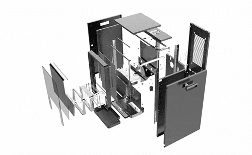
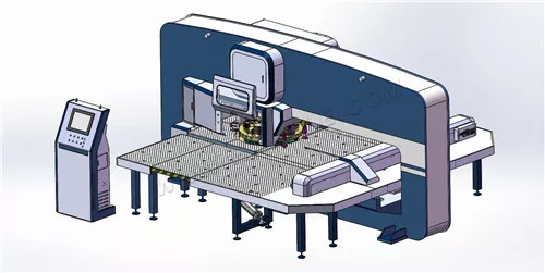
The assembly of a sheet metal component is the process of combining the various parts that make up the component and making each part correctly positioned, then fixed and connected so as to form a process that meets the requirements of the drawing. The assembly process of sheet metal components mainly includes assembly, welding (or riveting, etc.), straightening, painting and inspection processes.
Correct and reasonable assembly procedures are of great importance in determining the most reasonable method of operation for each process, in order to prevent and minimize deformation after assembly and welding, as well as to ensure product quality and improve labor productivity in all aspects. On the other hand, the diversity of the sheet metal components and the area of the plant, equipment, the technical condition of the operator, the materials and other factors determine that the method of assembly of sheet metal components is not unique and must be considered in a comprehensive manner depending on the specific circumstances of production in order to be finalized.
The 3 Elements of Assembly
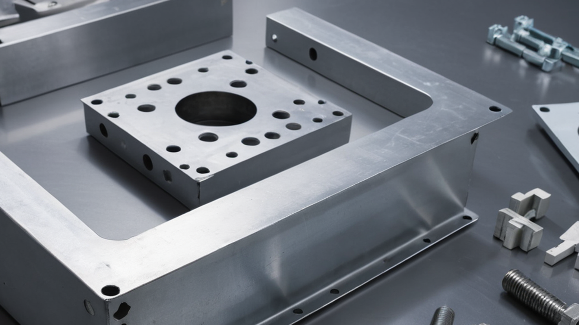
The assembly of sheet metal components, no matter what method is used to assemble the parts, has three elements: support, positioning and clamping.
1. Support. The selection of a reference surface to support the mounting surface of the component being assembled is called a support. Support is the first element of assembly, to solve the primary problem of where the product parts are assembled. For example, products with a flat surface are usually assembled on a platform or on a frame. The surface shape of complex products can be placed on a special mold for assembly, where the platform, frame, and mold are used to support the surface of the parts of the product being assembled, playing a supporting role in the assembly. When the support plays a positioning role, it is also called positioning support.
2. Positioning. The parts to be assembled are correctly fixed in the required position, called positioning. Because, the assembly is not an arbitrary combination of parts, but enables each part to obtain the correct position. Only through positioning and after fixing or connecting, the geometry of the product and the dimensions of each part can comply with the technical requirements specified in the drawings. The positioning of the parts of the product is the second element of the assembly.

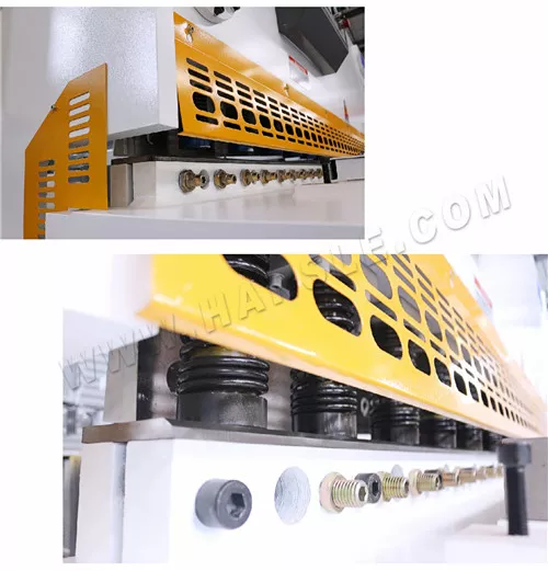
3. Clamping. In order to make the parts in the selected support and where the positioning position, fixed and connected no longer produce the position of movement, need to be a certain external force, called clamping. The purpose of clamping is to promote further correct positioning of the part through external forces. The clamping force required for clamping is usually achieved with a rigid fixture. The use of fixtures to help complete the assembly process is an important technical measure to obtain a qualified product. Clamping is therefore the third element of assembly.
The three elements of assembly are complementary to each other. The study of assembly technology always revolves around these three elements.
Positioning Principle
The purpose of positioning is to keep the assembled part (or parts) from moving freely in the required position. This means that the degree of freedom of the part to be assembled is constrained.
Any spatial object has six degrees of freedom in space, i.e. movement along three axes and rotation around them. For a part to have a fixed and constant position, the six degrees of freedom of the part must be restricted. For each degree of freedom restricted, the part comes into contact with a support point on the fixture, and restricting six degrees of freedom creates six support contact points. This method of limiting the six degrees of freedom of a part to six points is known as the six-point positioning principle.
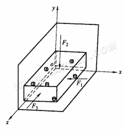
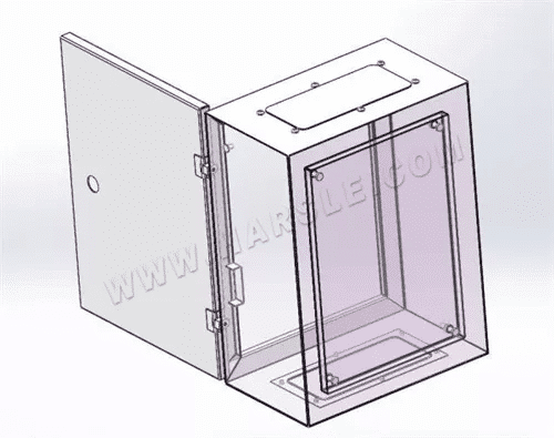
The diagram above shows the complete positioning of a rectangular part. xoz plane corresponds to three points limiting three degrees of freedom of the part (movement in the y-axis direction and rotation around the x and z axes). xoz plane is the main support surface of the rectangular part, while the surface of the part it contacts is called the main positioning reference (the large and dominant plane on the part). zoy plane limits two degrees of freedom of the part (movement in the x-axis direction and rotation around the y-axis).
The zoy plane is the guiding support surface of the rectangular part and the surface that touches it is called the guiding datum (the narrow, long plane of the workpiece). xoy plane restricts only one degree of freedom of the part (movement in the z-axis). xoy plane is the thrust support surface of the rectangular part and the surface that touches it is called the thrust data (the tiny plane of the workpiece). plane).
It should be noted that due to the different forms of steel structures and the many parts, the positioning points should be set in conjunction with the actual situation. The six-point positioning rule described above means that a part can be constrained to all its degrees of freedom using six support points. When a number of parts are combined together, a surface of part A can be used as the positioning reference surface of part B.
A surface of part B can be used as the positioning reference surface of part C. This is a common situation for parts positioning during steel assembly. Therefore, the positioning of parts in steel assembly is not every part to be implemented in the fixture six-point positioning.
Selection of The Assembly Datum
The face of the part in contact with the assembly platform is called assembly datum. It is equivalent to the primary positioning datum in six-point positioning. In general, the assembly reference surface can be selected according to the following principles:
1. The shape of the metal structure has a flat surface and a curved surface, the plane should be used as the assembly reference surface.
2. When there are several planes on the assembly, the larger plane should be selected as the assembly reference surface.
3. According to the role of the metal structure, the most important surface should be selected as the assembly reference surface, such as the machined surface.
4. The chosen assembly datum surface should be able to facilitate the positioning and clamping during the assembly of the part. Parts in the assembly process, if there is more than one surface can be the assembly reference surface, should be based on the actual production process to select the best surface as the assembly reference surface.