


Comprensión ESA S650 program section data is essential for anyone who wants to read, modify, or troubleshoot bending programs with confidence. The header section, the hidden bend type codes, and the piece‑related counters (Pieces done, To do, Measures, Devel.) all affect how the machine behaves and how the final part is calculated. In this guide, I’ll walk you through every component of ESA S650 program section data – what each value means, when to change it, and how it impacts your bending results. By the end, you’ll be able to navigate the ESA S650 program section data on the editor page like a pro.
Exploring the Header Section of ESA S650 Program Section Data
The header section sits at the top of the EDITOR page. It contains three key fields: program name, current bend, and current section. All of these are directly visible and can be modified by the operator.
Program Name – Identifying Your Job
The program name is an alphanumeric field that can hold up to 32 characters. If you leave it empty, the program becomes a temporary, unsaved program. You can also type the name of an existing program to load it directly. Using clear, descriptive names (e.g., “Bracket_90deg_2mm”) is a best practice for efficient ESA S650 program section data management.
- Minimum value: none (empty allowed)
- Maximum value: 32 characters
- Default value: empty
- Unidad: alphanumeric characters
Bend – Tracking the Current Bend Step
The “Bend” field shows which bend step is currently active. This number increases as you step through the program. You can change it manually to jump to a specific bend.
- Minimum value: 1
- Maximum value: depends on the number of bends in the section
- Default value: 1
- Unidad: pure number
Section – Working with Multiple Sides of the Sheet
The section field displays two numbers: the current section and the total number of sections. A “section” is a side of the sheet metal on which you are performing bends. For example, a simple box program may have two sections (horizontal bends and vertical bends).
- Format: current / total (e.g., 1/2)
- Por defecto: 1/1
- Unidad: pure number
Understanding the section data helps you organize complex parts. When you have multiple sections, the ESA S650 always starts bending from the section with the smallest sheet width. The header section gives you a quick reference to where you are in the program.
Decoding Supplementary Information (Not Settable by User Interface)
Beneath the visible header fields, the ESA S650 stores additional bend‑type information that you cannot change directly through the user interface. However, knowing what these codes mean allows you to interpret existing programs and troubleshoot unexpected behavior.
Bend Type Codes – What the Letters Mean
Each bend in the program has a type identifier. The following values may appear:
- N – Normal air bending. This is the standard bending mode.
- do – Radius bend (also called bumping a radius). Used for large cylindrical shapes.
- A – Conical radius bend. Combines a radius with a conical angle.
- R – Dutch folding (hemming) bend. Flattens the sheet onto itself.
- S – Coining bend. Uses high force to imprint the angle.
- I – Conical bend. Creates a conical shape, not a radius.
- 3 – Hammerle bend with bottom V‑die variable (bend on 3 points). A special bending method.
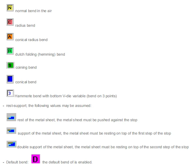
If you load a program and see a bend type that you did not expect, check whether you accidentally enabled a special function. For normal ESA S650 program section data, most bends should be type “N”.
Rest/Support Mode – How the Sheet is Held
The system also records how the sheet metal is positioned relative to the backgauge stops:
- I (Rest) – The sheet metal is pushed against the stop (normal mode).
- I (Support) – The sheet rests on top of the first step of the stop.
- I (Double support) – The sheet rests on top of the second step of the stop.
Although the same letter “I” appears, the context differs. In practice, the number of steps on your backgauge determines which support mode is available. This information is not settable via the UI, but it affects how the blank is positioned.
Default Bend Flag – D
The letter “D” indicates that the default bend is enabled. This means the system is using the standard bend parameters as defined in the machine configuration. This flag is normally present; you rarely need to change it.
By understanding these hidden codes, you can look at a program’s ESA S650 program section data and immediately know what kind of bending operation is programmed.
Working with Piece Data in ESA S650 Program Section Data
Section 6.3 covers the most practical fields for production tracking and measurement definitions. These are all settable by the user and directly impact how the machine counts parts and calculates blank sizes.
Pieces Done – Automatic Counter
This field shows how many pieces have already been completed from the current program. The control increments this value automatically after each finished part. However, you can also change it manually, for example, if you want to resume a batch that was partially completed earlier.
- Range: 0 – 9999
- Por defecto: 0
- Unidad: pure number
To Do – Batch Size Setting
Set the desired number of pieces you intend to produce. The control decreases this count after each finished piece. When “To do” reaches zero, the automatic execution stops, and you must press START again to continue (useful for pausing after a batch).
- Range: 0 – 9999
- Por defecto: 0
- Unidad: pure number
Using both counters together gives you hands‑free batch production. For example, set “To do” = 50, run the program, and the machine will stop automatically after the 50th part.
Measures – How the Workpiece is Described
This field is critical for accurate unfolding. It accepts three values:
- 0 – External measurements. The stretch of the sheet metal is considered. The program calculates the blank size by subtracting the development from the total length. This is the most common mode for standard bending.
- 1 – Neutral fiber measurements. The stretch is no considered. Use this when you have exact neutral axis data from a test.
- 2 – Internal measurements. The stretch is considered, similar to mode 0, but based on internal dimensions.
Choosing the correct measurement mode is one of the most important decisions when entering ESA S650 program section data. For most shops, mode 0 (external) works well. Mode 1 is used only when you have verified neutral fiber data.
Devel. – Development Length or Blank Size
The meaning of the “Devel.” field depends on the program type and the Measures value:
| Program Type | Measures value | Devel. meaning |
|---|---|---|
| Numérico | 0 or 2 | Size to subtract from total sheet length to get blank size |
| Numérico | 1 | No value calculated (field empty) |
| Gráfico | 0 or 2 | Total length of sheet metal including stretch (cutting length or blank size) |
| Gráfico | 1 | Total length of sheet metal without stretch |
- Range: 0 – 9999
- Unidad: mm or inch (depending on machine settings)
If you notice that your calculated blank size is wrong, double-check the Measures mode. An incorrect setting (e.g., using mode 1 when you should use mode 0) will lead to parts that are too long or too short.
Preguntas frecuentes (FAQ)
Can I change the bend type (N, C, R, etc.) manually?
Not directly in the header section. The bend type is determined by the function you choose when creating the bend (e.g., pressing “Bumping a Radius” sets type C). To change an existing bend type, you generally need to delete the bend and recreate it with the desired function.
Why does my graphic program show a different “Devel.” value than I expected?
Check the “Measures” setting. If it is set to 1 (neutral fiber), the development does not include stretch. Switch to 0 or 2 to include stretch. Also verify that your material thickness and bend radius are correct.
Conclusión
Mastering ESA S650 program section data gives you complete control over program identification, bend type interpretation, production counting, and measurement definitions. The header section (program name, bend, section) helps you navigate multi‑section jobs. The hidden bend type codes (N, C, R, S, I, A, 3) allow you to recognize special operations. The piece data fields (Pieces done, To do, Measures, Devel.) let you manage batch production and choose the correct unfolding method. By understanding each field – its range, default, and meaning – you can avoid common mistakes like mis‑counting parts or using the wrong development length.
Now that you have a solid understanding of ESA S650 program section data, I encourage you to open an existing program on your machine and examine its header and piece data. Change the Measures value from 0 to 2 and see how Devel. updates. Set a small batch size and watch the counter work. For deeper dives into axis data or work data, stay tuned for the next articles in this series. If you have any questions, our apoyo técnico team is always available to help.


