


Correct adjustment of the ESTUN E315P Auxiliary Axis is important for maintaining bending accuracy when press brake deflection occurs under load. In the E315P control system, the C-axis serves as an auxiliary axis for deflection compensation. It adjusts the lower table to compensate for deformation caused by bending forces and helps maintain more uniform pressure across the workpiece.
The E315P supports both mechanical and hydraulic compensation methods for the C-axis. In mechanical compensation mode, the controller uses motor feedback voltage and calibrated displacement data to determine the actual compensation position. Understanding this relationship is essential when configuring or checking the ESTUN E315P Auxiliary Axis.
What Is the ESTUN E315P Auxiliary Axis?
The E315P divides controlled axes into servo axes and an auxiliary axis.
The X, Y, and R axes are servo axes driven by servo motors. They are responsible for movements such as backgauge positioning and ram movement.
The C-axis is classified as the auxiliary axis. Its primary function is to provide deflection compensation during bending.
Unlike the X, Y, and R axes, the C-axis does not simply position a standard machine component. Instead, it adjusts the lower table compensation system according to the required bending conditions.
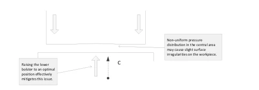
Therefore, the ESTUN E315P Auxiliary Axis is closely associated with maintaining bending accuracy across the workpiece.
Why Does the Press Brake Need C-Axis Compensation?
During bending, the upper die applies considerable force to the workpiece and machine structure. Under this load, deformation can occur across the working length.
The bending force may become concentrated toward both ends while the pressure around the center of the sheet becomes less uniform.
The C-axis compensation system is designed to counteract this effect.
By lifting or adjusting the lower table appropriately, the compensation system helps correct the deformation generated during bending. This allows the tooling to maintain a more suitable relationship across the bending length.
For this reason, correct ESTUN E315P Auxiliary Axis adjustment can contribute directly to consistent bending results.
What Compensation Modes Does the E315P Support?
The E315P provides two C-axis compensation methods:
- Mechanical Compensation
- Hydraulic Compensation
Both methods are intended to compensate for machine deflection, but their actuation methods are different.
Mechanical compensation uses a motor to control the movement of the lower table compensation mechanism.
Hydraulic compensation uses a hydraulic method to provide the required compensation.
The appropriate method depends on the actual mechanical and hydraulic design of the press brake.
How Does Mechanical Compensation Work?
Mechanical compensation is an important part of the ESTUN E315P Auxiliary Axis system.
In this mode, a motor controls the movement of the lower table compensation mechanism. The E315P determines the compensation position using feedback from the C-axis motor.
The controller continuously reads a feedback voltage ranging from 0 to 10 V.
However, voltage alone does not directly represent the physical compensation distance. The system therefore requires a defined relationship between feedback voltage and actual movement.
This relationship is established through Calibration Voltage Und Calibration Distance.
What Are Calibration Voltage and Calibration Distance?
Calibration Voltage and Calibration Distance allow the E315P to establish the relationship between electrical feedback and physical C-axis movement.
During setup, specific voltage values are associated with corresponding compensation distances.
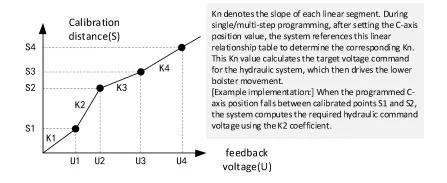
The controller can then use these calibration points to determine the actual position of the ESTUN E315P Auxiliary Axis from the received motor feedback voltage.
This relationship is represented in the manual as a series of linear sections.
Each section has its own slope, identified by values such as K1, K2, and other corresponding K values.
This means that the controller does not need to treat the entire compensation range as one single fixed relationship. Instead, it can determine the appropriate linear section according to the programmed C-axis position.
How Does the Voltage-Distance Relationship Work?
The relationship between Calibration Voltage and Calibration Distance allows the controller to convert electrical feedback into an estimated physical position.
Suppose several calibration points are established across the C-axis travel range. The controller forms linear relationships between adjacent calibration points.
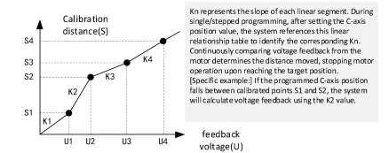
Each interval therefore has a corresponding slope.
When the programmed compensation position falls within one of these intervals, the E315P identifies the relevant section and uses its corresponding relationship.
For example, if the programmed C-axis position lies between calibration points S1 and S2, the controller uses the corresponding K2 relationship shown in the manual.
This allows the ESTUN E315P Auxiliary Axis to determine movement based on the calibration data rather than relying only on a single voltage value.
How Does the C-Axis Reach the Target Position?
The mechanical compensation process can be understood as a continuous feedback cycle.
1. Servo Axes Complete Positioning
When the machine starts the relevant operating process, the servo axes first move to their required positions.
2. The E315P Reads C-Axis Feedback
The controller continuously receives the 0–10 V feedback voltage from the C-axis motor.
This voltage provides the information required to determine the current compensation position.
3. The Controller Calculates the Position
Using the predefined Calibration Voltage and Calibration Distance relationship, the E315P determines how far the compensation mechanism has moved.
The appropriate linear relationship is selected according to the programmed C-axis position.
4. The Motor Continues Moving
The controller continuously compares the calculated position with the programmed target.
As long as the target has not been reached, the compensation motor continues to operate according to the control requirements.
5. The Motor Stops at the Target
Once the feedback indicates that the required compensation position has been reached, the controller stops the motor.
This closed feedback process allows the ESTUN E315P Auxiliary Axis to reach the programmed compensation position.
How Does the Auxiliary Axis Work During Programming?
During single-step or multi-step programming, the operator can set the required C-axis position value.
Once this value has been programmed, the controller references the established voltage-distance relationship.
It identifies which calibration interval contains the requested position and uses the corresponding linear relationship for position calculation.
While the motor moves, the E315P continuously monitors its voltage feedback. The controller converts this feedback into movement information and compares it with the programmed target.
When the calculated movement reaches the required C-axis position, motor movement stops.
This process connects the programmed compensation value with the actual movement of the lower table compensation mechanism.
What Should Be Checked Before Adjusting the Auxiliary Axis?
Before changing ESTUN E315P Auxiliary Axis settings, technicians should first confirm which compensation system is installed on the machine.
Mechanical and hydraulic compensation should not be treated as identical configurations.
For mechanical compensation, particular attention should be paid to the relationship between Calibration Voltage and Calibration Distance. Incorrect calibration data may prevent the controller from correctly determining the physical C-axis position from the feedback signal.
Technicians should also retain the original machine parameters before making changes and ensure that the configured values correspond with the actual compensation mechanism.
Adjustment should therefore be based on the specific press brake configuration rather than parameters copied directly from another machine.
Frequently Asked Questions(FAQ)
Can Calibration Data Be Copied From Another Press Brake?
It is not recommended. The Calibration Voltage and Calibration Distance relationship should correspond to the actual compensation mechanism of the specific machine. Even similar machines may have different calibration characteristics.
What If the C-Axis Feedback Voltage Is Abnormal?
For mechanical compensation, the E315P relies on a 0–10 V feedback signal to determine the compensation position. If the feedback is missing or abnormal, check the related electrical connections, feedback signal, and compensation mechanism before changing calibration parameters.
When Should the Auxiliary Axis Configuration Be Checked?
The configuration is particularly worth checking during machine commissioning, after relevant electrical or mechanical components have been replaced, after controller parameters have been restored, or when the C-axis position or compensation response is clearly abnormal.
Abschluss
The ESTUN E315P Auxiliary Axis provides C-axis deflection compensation to help maintain consistent bending accuracy across the working length of the Abkantpresse. Depending on the machine design, the E315P can work with mechanical or hydraulic compensation.
In mechanical compensation mode, accurate positioning depends on the relationship between Calibration Voltage and Calibration Distance. The controller continuously evaluates motor feedback and uses the corresponding linear relationship to determine the actual compensation position.
When adjusting the ESTUN E315P Auxiliary Axis, technicians should preserve the original parameters, verify the actual compensation system, and ensure that calibration data matches the machine. Correct configuration allows the C-axis to respond accurately to programmed compensation values and provides a reliable foundation for consistent bending performance.


