


Applying ESA S650 axis data correctly is the key to achieving precise bend angles, accurate backgauge positions, and collision‑free operation. Whether you are setting up a new numeric program or fine‑tuning an existing one, understanding the relationship between axis parameters (Y1/Y2, X1/X2, R1/R2, Z1/Z2, A1/A2) and the material data (width, thickness, resistance) allows you to avoid common errors like incorrect springback compensation or retract collisions. In this guide, I’ll walk you through every field in the section general data and the axis/angle data section – what each value means, when to modify it, and how to apply corrections correctly. By the end, you’ll be able to confidently adjust Y‑axis angles, X‑axis positions, and special axes (crowning, follower arms, Hammerle M‑axis) on your ESA S650 control.
Understanding Section General Data Before Applying ESA S650 Axis Data
The section general data defines the physical properties of the workpiece and the tooling used for each bend. Correctly setting these values is a prerequisite for applying ESA S650 axis data because the axis calculations depend on them.
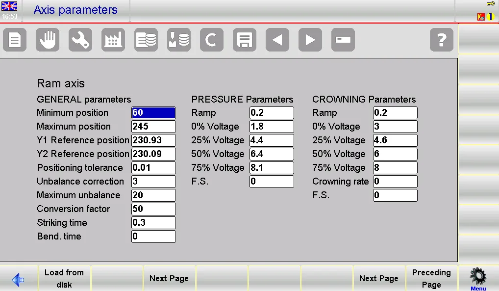
Width, Thickness, and Resistance – The Material Triangle
These three fields directly influence how the control calculates the Y‑axis lower dead center (L.D.C.) and the stretch for X‑axis corrections.
- Ancho (0 – 99999.9 mm) – The sheet metal width at the bend point. This affects the tonnage calculation and machine deflection.
- Espesor (0.01 – 99.99 mm) – Enter the actual material thickness. Even a 0.1 mm error can lead to incorrect bend angles.
- Resistencia (0 – 150 kg/mm²) – Use the suggested defaults: 25 for aluminium, 45 for iron, 70 for stainless steel. If your final angle is off, check this value first before adjusting ESA S650 axis data.
Material – Automatic or Manual Selection
The “Material” field (1–9) is automatically initialized based on the resistance value you entered. However, you can override it manually. The mapping is:
- 1,4,7 = aluminium types 1,2,3
- 2,5,8 = iron types 1,2,3
- 3,6,9 = stainless steel types 1,2,3
When applying ESA S650 axis data, remember that changing the material later does not automatically update the resistance – you must create a new program to regenerate automatically.
Station – Using Multiple Work Stations
Station (0–4) tells the control which work station (defined in the tooling page) is active. Station 0 means no station is used – the machine centers the Z‑axes. Stations 1–4 allow automatic Z positioning for off‑center bending. This is essential when you have multiple tool sets mounted.
Die, V‑die, and Punch – Tooling References
- Morir – Name of the die (up to 9 alphanumeric characters). Must exist in the tool library.
- V‑die – Number of the V‑die (if the die has multiple V‑grooves). The width of the selected V‑die appears to the right.
- Puñetazo – Name of the punch (up to 9 characters).
Incorrect tool selection will make all ESA S650 axis data invalid because the control uses tool geometry to calculate the Y‑axis L.D.C. Always verify that the tool names match your physical setup.
Breaking Down the Axis and Angle Data Section
This section contains the core parameters that define each bend. Properly applying ESA S650 axis data means understanding every Y, X, R, Z, and A field.
Y‑Axis Data – Angle, L.D.C., and Corrections
The Y1 and Y2 cylinders control the ram movement.
- Ángulo Y1 (–179.9° to 180.0°) – Desired bending angle. For a standard 90° bend, enter 90.0.
- L.D.C. Y1 (0.00 – 9999.99 mm) – The ram position (lower dead center) that the machine calculates to achieve the set angle. You rarely modify this directly; the control computes it from angle, tooling, and material.
- Y1 Corrections (–90.0° to 90.0°) – Manual angle correction. If your measured angle is 89°, enter +1.0° to open the bend further. This value is also available on the CORRECTIONS page.
The same fields exist for Y2 (right cylinder). On most machines, Y1 and Y2 move together, but corrections can be applied independently to compensate for mechanical tilt.
Consejo profesional: When applying ESA S650 axis data, always start with small corrections (±0.5°) and re‑measure. Large jumps can cause over‑correction.
X‑Axis Data – Final Position, Retract, and Corrections
The X1 and X2 axes position the backgauge fingers.
- X1 Final (–99.99 to 9999.99 mm) – The distance from the bend line to the backgauge. This defines the flange length.
- X1 Retract (0 – 999.99 mm) – How far the backgauge moves backward after the ram passes the pinch point. This prevents the workpiece from hitting the fingers during bending.
- X1 Corrections (–999.99 to 9999.99 mm) – Correction to the X position, typically used to compensate for material stretch. When MEASURES=0, this correction equals the stretch value. In support mode, the backgauge length is automatically added.
X2 works identically for the right‑side backgauge. Correctly applying ESA S650 axis data requires setting retract values high enough to avoid collisions but low enough to keep cycle times short.
R‑Axis Data – Height for Rest/Support
- R1 Final y R2 Final (–99.99 to 9999.99 mm) – Vertical position of the backgauge fingers (height). Used when the sheet must rest on a step rather than be pushed against the stop. This is critical for bending large panels.
Z‑Axis Data – Opening Width for Wide Sheets
- Z1 Final y Z2 Final (–99.99 to 9999.99 mm) – Lateral positions of the backgauge fingers. Z1 moves left, Z2 moves right. They open to support wide sheets and close for narrow ones.
A‑Axis Data – Special Functions (Crowning, Follower Arms, Hammerle)
The A1 and A2 fields change meaning depending on the machine configuration:
- Mechanical crowning (Operating Mode = Mechanical crowning) – A1 Final is the crowning amount in % of maximum range (0–100%) or mm/inch. Compensates for deflection.
- Hammerle press brake (M‑axis) – A1 Final is the position of the M‑axis (variable V‑die depth) in mm/inch. Changes the die depth to adjust the bend angle.
- Follower arms (Operating Mode = Follower arm) – A1 Final and A2 Final (0–90 degrees) are the angles of the follower arms relative to the sheet support plane. These help guide the sheet during large radius or hemming bends.
When applying ESA S650 axis data for these advanced axes, consult your machine’s specific manual – the behavior depends on optional hardware.
Step‑by‑Step – How to Apply ESA S650 Axis Data Correctly in a Program
Step 1 – Enter Material and Tooling (Section General Data)
In the numeric program editor, fill in:
- Width, Thickness, Resistance (or Material number).
- Station (if using multiple work stations).
- Die name, V‑die number, Punch name.
Step 2 – Set the Desired Bend Angle (Y1 Angle)
Enter the target angle in the Y1 Angle field (and Y2 Angle if independent). Do not touch L.D.C. Y1 – it will be calculated automatically.
Step 3 – Define the Flange Length (X1 Final)
Enter the required flange length in X1 Final. For the first bend, this is the distance from the edge to the bend line.
Step 4 – Set Retract and Corrections as Needed
- Adjust X1 Retract to a safe value (e.g., 20 mm) to avoid collision.
- If you already know a stretch correction from previous jobs, enter it in X1 Corrections.
Step 5 – Run a Test Bend and Measure
After bending, measure the actual angle and flange length. If the angle is off, calculate the correction: correction = desired angle – measured angle. Enter this in Y1 Corrections. If the flange is too long or short, adjust X1 Corrections.
Step 6 – Apply Corrections and Save
After updating corrections, run another test bend. Repeat until dimensions are within tolerance. Then save the program.
Preguntas frecuentes (FAQ)
Why is my Y1 Angle not matching the actual bend angle?
Check your material resistance, thickness, and tooling first. If those are correct, apply a Y1 Correction. Also, ensure your machine has been calibrated (T.D.C., mute, pinch point).
Can I set Y1 and Y2 angles differently?
Yes, if your machine has independent Y‑axis cylinders. This is used to correct for tilt or to produce tapered bends. However, for standard bending, set them equal.
How do I know if my machine has a crowning axis?
Check the Operating Mode in the configuration parameters. If “Mechanical crowning” is available, you will see the A1 field. Otherwise, ignore it.
Conclusión
Applying ESA S650 axis data correctly transforms a rough program into a precise, collision‑free bending routine. By mastering the section general data (width, thickness, resistance, material, station, tools) and the axis/angle data (Y‑angle + L.D.C. + corrections, X final + retract + corrections, R, Z, and optional A axes), you can troubleshoot angle errors, flange length deviations, and backgauge interference with confidence. Always start with accurate material and tooling values, then use small incremental corrections. Remember to run test bends and measure – the control’s calculations are only as good as the input data.
Now that you know how to apply ESA S650 axis data correctly, I encourage you to open a simple numeric program and experiment with Y1 Corrections and X1 Retract. Watch how the ram position and backgauge behavior change. For further learning, refer to the work data section to understand mute point and pinch point settings – they directly affect how the axis data is executed during the bend cycle. If you have any questions, our HARSLE technical support team is always ready to assist.


