


Learn how to set HS18T press brake parameters, select V-dies, adjust bending compensation, and program multiple bending steps with HARSLE.
How to Set HS18T Press Brake Parameters Easily?
Wstęp
Accurate configuration of HS18T press brake parameters is essential for achieving consistent bending results when processing metal sheets with different thicknesses, dimensions, and bending requirements. By understanding the controller’s basic functions, operators can prepare the machine more efficiently, select appropriate tooling, and make necessary corrections after test bending.
In this HARSLE tutorial, we demonstrate how to configure material settings, select punches and dies, adjust bending angles, set backgauge positions, and create multi-step bending programs using the HS-18T controller. The video also includes practical examples involving different plate thicknesses and a three-step bending sequence.
Understanding these functions helps operators establish a more systematic approach to daily press brake setup while reducing unnecessary adjustments during production.
Understanding the HS-18T Press Brake Parameters Control Interface
The HS-18T controller provides an integrated interface for configuring the essential parameters required during press brake operation. Before beginning production, operators should become familiar with the available settings and understand how each parameter relates to the workpiece and installed tooling.
To prepare the machine, start the hydraulic pump and press the Start button on the controller. Once the system displays OK, the controller indicates that it is ready for operation.
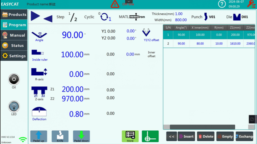
The main interface contains several important settings, including material selection, plate thickness, plate width, upper punch selection, lower die selection, target bending angle, and backgauge positioning.
Correctly configuring these HS18T press brake parameters helps ensure that the programmed bending conditions correspond to the actual material dimensions and tooling configuration.
How to Configure Basic HS18T Press Brake Parameters
Material and Plate Dimension Settings
The first stage of parameter configuration involves selecting the material and entering the dimensions of the metal sheet being processed. Operators should enter the actual plate thickness and width according to the workpiece specifications rather than relying on previously stored values.
These settings are particularly important when changing between materials of different thicknesses because the corresponding tooling selection and bending requirements may also change.
Accurate material and dimension information provides the foundation for subsequent operations, making it essential to verify these values before continuing with the bending setup.
Upper Punch and Lower Die Selection
After entering the material information, operators should select the upper punch and lower die that correspond to the tooling physically installed on the press brake.
The controller provides separate selection areas for punches and dies, allowing operators to configure the appropriate combination according to the bending requirements.
Because different tooling profiles and V-openings are designed for different applications, incorrect selection may lead to discrepancies between the programmed settings and actual bending conditions.
When configuring HS18T press brake parameters, operators should therefore confirm that the selected tooling data matches the installed punch and die before proceeding.
Target Bending Angle Settings
The target bending angle should be entered according to the workpiece drawing and the required finished geometry. Depending on the application, operators may enter angles such as 90°, 100°, or 120° directly into the corresponding setting field.
After the initial configuration, a test bend should be performed to verify whether the actual bending result matches the programmed angle.
If a deviation is detected, the controller provides compensation functions that allow the operator to make corrections based on the measured result.
How to Select the Correct Die V-Opening
Selecting a suitable lower die is an important part of configuring HS18T press brake parameters, particularly when processing metal sheets with different thicknesses.
A commonly used guideline for conventional air bending is V = 8 × t, where V represents the lower die opening width and t represents the plate thickness.
For example, a 1 mm plate can be paired with a V8 die, while a 5 mm plate corresponds to a V40 die under this reference guideline.
In the video demonstration, the operator first enters a plate thickness of 5 mm and configures the corresponding workpiece dimensions. After selecting the V40 lower die and confirming the tooling parameters, the target bending angle and backgauge positioning dimension are entered according to the processing requirements.
The same general procedure is demonstrated for thicker materials. When bending an 8 mm plate, the operator changes the thickness setting to 8 mm and selects a V64 die. For a 10 mm plate, a V80 die is selected before the remaining bending parameters are configured.
Although this proportional relationship provides a convenient starting point, actual die selection should also consider material properties, bending methods, desired inside radius, minimum flange length, and tooling capacity.
How to Adjust Bending Angle Compensation
Even when HS18T press brake parameters have been configured correctly, the measured bending angle may differ slightly from the target value because of material characteristics, springback, and actual processing conditions.
The controller provides an angle compensation function that allows operators to correct these deviations after performing a test bend.
For example, if the target bending angle is 90° but the measured result is 93°, the video demonstrates entering a compensation value of -3° to correct the difference.
Alternatively, operators can use the measured-angle correction function, which allows them to enter the actual measured angle directly. The controller then calculates and applies the corresponding negative compensation according to its demonstrated correction method.
These adjustment options make it easier to refine the bending result without manually recalculating every parameter. However, the compensation direction described here follows the demonstrated HS-18T interface and should not automatically be applied to other controller models.
Backgauge Positioning and Dimension Compensation
Backgauge positioning is another essential component of HS18T press brake parameters, as it establishes the positioning reference used to obtain the required bending dimension.
The controller provides an X-axis positioning field in which operators can enter the desired dimension according to the workpiece drawing.
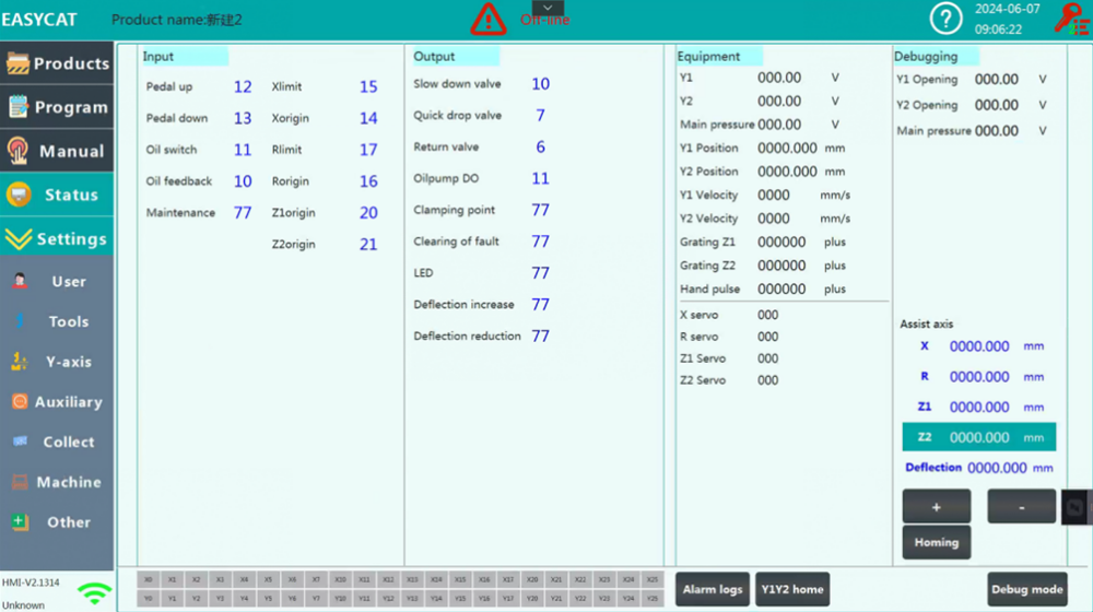
For example, when the programmed positioning dimension is 50 mm but the measured flange length after a test bend is 51 mm, the operator can use the backgauge compensation function to correct the dimensional deviation.
The tutorial also introduces outside and inside positioning dimension modes. According to the demonstrated controller settings, the reference difference between these two modes corresponds to the previously entered plate thickness.
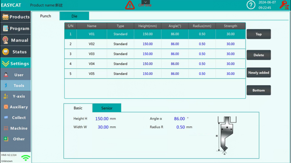
Operators should select the appropriate positioning mode based on the workpiece requirements and verify the actual result after bending.
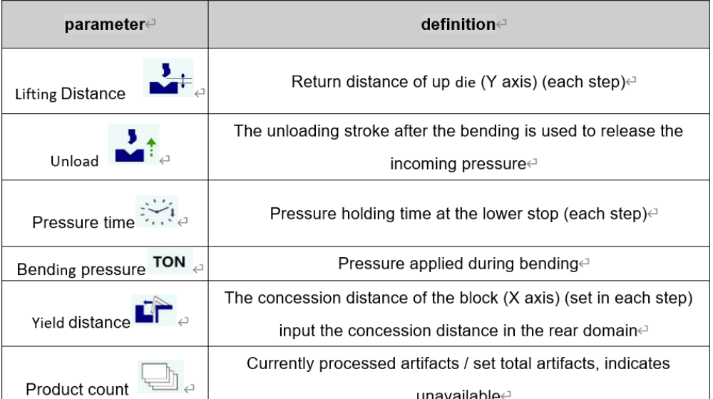
Another available setting is pressure holding time, which determines how long pressure is maintained after the ram reaches bottom dead center.
How to Add Multiple Bending Steps
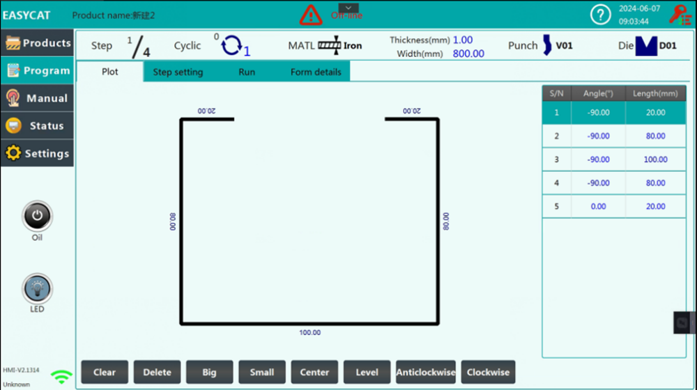
For workpieces requiring several bending operations, the HS-18T controller provides a multi-step programming function that allows different angles and positioning dimensions to be configured within a single program.
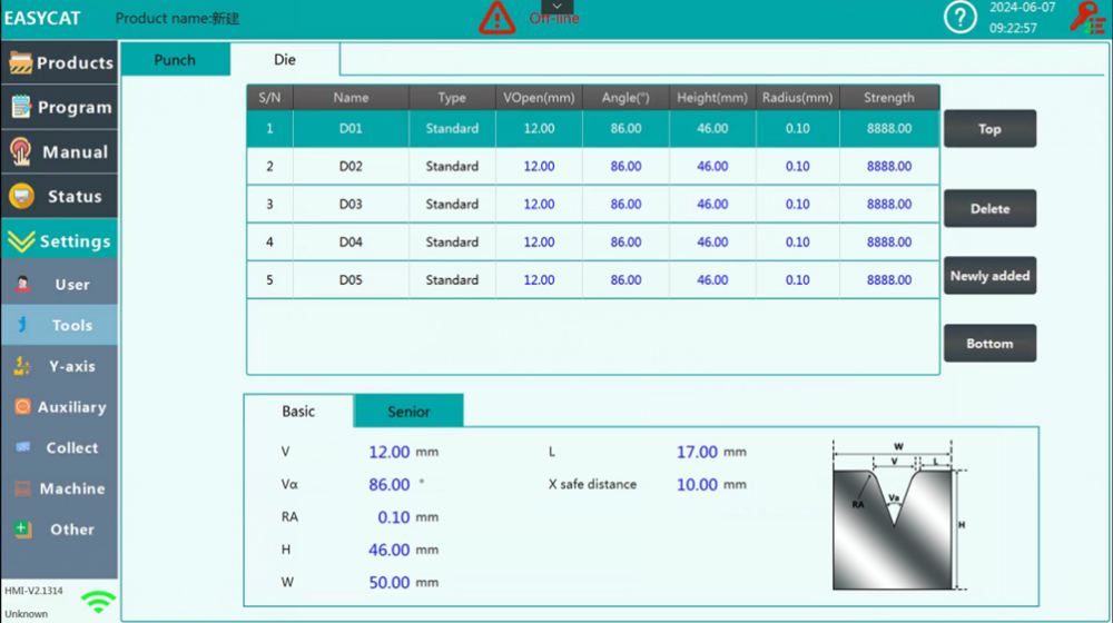
When setting up HS18T press brake parameters for multi-step production, operators should first complete five basic settings: material, plate thickness, plate width, upper punch, and lower die.
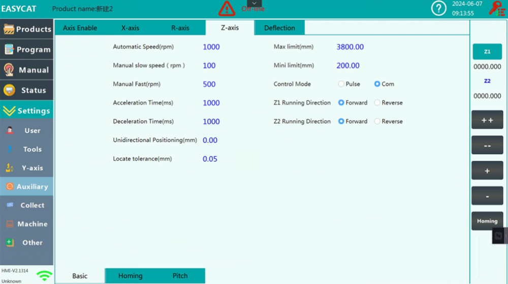
After confirming these parameters, additional bending steps can be created through the Add Step function. The interface displays the current step and the total number of programmed steps, while navigation buttons allow operators to move between individual operations.
Each bending step can be configured independently, making it possible to prepare workpieces that require different bending angles and flange dimensions within the same processing sequence.
HS-18T Three-Step Bending Program Example
The tutorial demonstrates multi-step programming using a 2 mm metal plate, showing how operators can configure three different bending operations within one program.
After entering the plate thickness and selecting the appropriate lower die, the operator begins by configuring the first bending step with a target angle of 90° and a positioning dimension of 15 mm.
Once the first step has been completed, the operator switches to the second step and enters a bending angle of 135°, together with a positioning dimension of 20 mm.
The third step follows the same procedure, but the target angle is changed to 170° and the positioning dimension is set to 30 mm.
This example demonstrates how HS18T press brake parameters can be configured individually for each bending step while maintaining the basic material and tooling settings established at the beginning of the program.
After completing all three steps, the operator should review the programmed values, confirm that the bending sequence matches the workpiece requirements, and press Start. Once the controller finishes loading and displays OK, the machine is ready for the test bending operation.
Three-Step Continuous Bending Demonstration
After the multi-step program has been prepared, the video demonstrates the bending process using a sample plate.
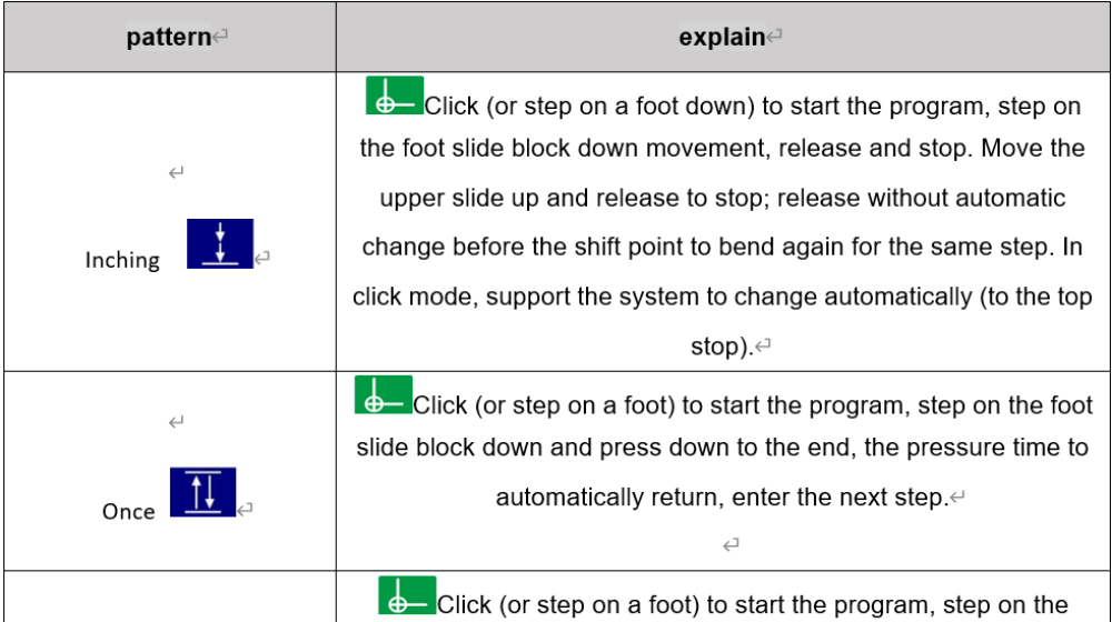
The first operation follows the programmed 90° bending angle and 15 mm positioning dimension. After the initial bend, the controller automatically advances to the second step and subsequently to the third step according to the programmed sequence.
This function reduces the need to manually re-enter bending angles and positioning dimensions between operations, helping operators manage multi-step bending tasks more efficiently.
Before beginning production, operators should perform the necessary safety checks, confirm that all emergency stop buttons have been released, and ensure that the hydraulic pump is operating normally.
Although the controller manages the programmed step sequence, the operator must still position the workpiece correctly and follow the established machine safety procedures throughout the bending process.
Wniosek
Understanding and correctly configuring HS18T press brake parameters is essential for achieving consistent bending results and improving daily press brake operation.
By selecting suitable tooling, entering accurate material dimensions, adjusting bending compensation, and creating multi-step programs, operators can prepare the HS-18T controller for different bending applications with greater efficiency.
The practical examples demonstrated in this tutorial provide a useful reference for both basic parameter configuration and multi-step bending operations.
To learn more about the complete operating procedure, watch the HS-18T operation tutorial.
For additional CNC press brake tutorials, operating guides, and technical support, visit HARSLE.


