


The CybTouch 8 Punches and Dies library allows operators to select, manage, and configure the tooling used for press brake bending operations. By choosing the correct punch and die, the controller can automatically calculate the required Y-axis and X-axis positions, improving programming accuracy and reducing setup time. In this guide, I will explain how to browse the CybTouch 8 Punches and Dies library, understand the displayed tooling information, and select the appropriate tools for different bending applications. Mastering this function helps ensure consistent bending results while simplifying daily production and tooling management.
Understanding CybTouch 8 Punches and Dies
The CybTouch 8 Punches and Dies library is a key part of the controller’s Tool Management system. It stores the geometric and functional information of punches and dies used on the press brake, allowing the controller to calculate bending positions automatically during program creation.
Once a punch and die have been selected, the CybTouch 8 controller uses their dimensions together with the material properties and bend angle to calculate the required Y-axis position, Eje X backgauge position, bending force, and other process parameters. Selecting the correct tooling is therefore essential for achieving accurate and repeatable bending results.
The CybTouch 8 Punches and Dies interface also allows operators to browse existing tooling libraries, review tool specifications, and quickly assign the appropriate tools to the current bending program.
Browsing the Punch Library
The Punch Library provides a centralized location for managing all punches available on the machine.
From the Bend Numerical Page, operators can open the Punch Library and browse the existing punch database using the navigation arrows. Each punch entry contains both graphical and numerical information to help identify the correct tooling.
Typical punch information includes:
- Punch name
- Dirección de montaje del punzón
- Basic tool dimensions
- Altura
- Radio
- Tonnage capacity
- Bottoming compatibility
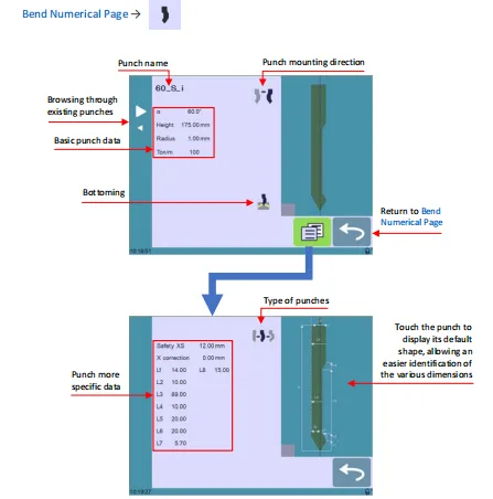
The graphical preview displayed on the right side of the screen makes it easier to distinguish between different punch profiles, especially when several tools have similar dimensions.
By reviewing both the numerical data and graphical representation, operators can quickly verify whether the selected punch matches the production requirements.
Selecting the Correct Punch
Selecting a punch is straightforward.
Operators simply browse the available punch library, highlight the desired tool, and return to the Página numérica de curvatura.
Once selected, the punch becomes part of the active bending program, and its dimensions are automatically used in subsequent bending calculations.
Using the correct punch provides several advantages:
- More accurate bend angle calculations
- Correct beam positioning
- Improved programming efficiency
- Reduced setup errors
- Better bending consistency
If multiple punch types are available, operators should always verify the tool profile and dimensions before confirming the selection.
Understanding Punch Information
Each punch record contains both basic and detailed information.
The basic information typically includes the punch angle, height, radius, and maximum tonnage rating. More detailed parameters can also be viewed to verify the exact tool geometry.
Depending on the machine configuration, additional settings may include:
- Tool safety distance
- Mounting orientation
- Bottoming capability
- Tool-specific dimensions
These values are used internally by the controller to perform automatic calculations during program generation.
Using accurate tooling information helps minimize programming corrections and reduces the need for manual adjustments during production.
Browsing the Die Library
The Die Library operates similarly to the Punch Library and stores all lower dies available for the machine.
From the Bend Numerical Page, operators can open the Die Library and browse existing dies using the navigation buttons.
Each die record displays important information, including:
- Die name
- Dirección de montaje de la matriz
- V-opening (Ve)
- Die height
- Radio
- Maximum tonnage
- Bottoming compatibility
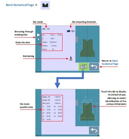
A graphical preview is also provided, allowing operators to visually confirm the selected die before returning to the program page.
This graphical representation reduces the possibility of selecting the wrong tooling, particularly in production environments where multiple dies have similar specifications.
Selecting the Correct Die
After locating the required die, operators simply confirm the selection and return to the Bend Numerical Page.
The selected die immediately becomes part of the active bending program, allowing the controller to calculate the proper bending parameters automatically.
Choosing the correct die directly affects:
- Bend angle accuracy
- Fuerza de flexión requerida
- Crowning calculation
- Tool clearance
- Material positioning
- Backgauge calculations
For this reason, it is recommended to verify both the graphical preview and numerical specifications before beginning production.
Why Tool Selection Matters
The CybTouch 8 Punches and Dies library does much more than simply record tool names. Every punch and die contains dimensional information that the controller uses to calculate important bending parameters automatically.
Incorrect tooling selection may lead to:
- Incorrect bend angles
- Improper beam positions
- Excessive bending force
- Tool interference
- Reduced part accuracy
- Additional programming corrections
By selecting the appropriate punch and die before programming begins, operators can significantly reduce setup time while improving repeatability and overall production efficiency.
Best Practices for Managing CybTouch 8 Punches and Dies
To maintain an organized tooling database and ensure reliable bending performance, operators should follow several best practices when using the CybTouch 8 Punches and Dies library.
Recommended practices include:
- Keep the punch and die libraries up to date.
- Verify tool dimensions before selecting a tool.
- Use graphical previews to confirm tool profiles.
- Check the mounting direction before production.
- Ensure the selected punch and die match the actual tools installed on the machine.
- Review bottoming compatibility when using bottoming operations.
- Use consistent tool naming conventions to simplify future program creation.
Maintaining an accurate tooling library allows the CybTouch 8 controller to perform precise automatic calculations, helping reduce programming time, improve bending accuracy, and ensure consistent production results across different workpieces.
Preguntas frecuentes (FAQ)
What is the purpose of the graphical tool preview?
The graphical preview helps operators quickly identify the selected punch or die by displaying its profile and dimensions. This reduces the risk of selecting the wrong tool, especially when multiple tools have similar specifications.
Can I edit punch or die information from this page?
This page is primarily intended for browsing and selecting existing tools. Creating or modifying punch and die data is performed through the dedicated tool editing functions, which are covered separately in the CybTouch 8 Tool Creation guide.
How can I keep the tooling library organized?
Maintain consistent tool names, remove obsolete entries when appropriate, and update the library whenever new punches or dies are added. A well-organized tooling library speeds up programming and helps prevent tooling selection errors.
Conclusión
The CybTouch 8 Golpes and Dies library is an essential part of the controller’s Tool Management system. By providing detailed information about available punches and dies, it enables the controller to calculate bending parameters automatically and improves the accuracy of every bending program.
Understanding how to browse, identify, and select the correct tooling helps reduce programming errors, shorten setup time, and ensure consistent production quality. Using the graphical previews together with the detailed tool specifications also makes it easier to verify that the selected punch and die match the tooling installed on the press brake.


