


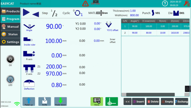
The ET18 Programming Page is the main interface for entering bending parameters and organizing machining steps on an electro-hydraulic press brake. It displays essential information such as bending angle, backgauge position, axis values, tooling selection, and material dimensions.
Understanding this interface helps operators prepare bending programs, review machining requirements, and manage multiple bending steps more efficiently.
This guide introduces the main functions of the ET18 controller’s programming interface and explains how operators can use its available settings during everyday prensa plegadora operación.
Understanding the ET18 Programming Page Interface
The ET18 Programming Page provides a centralized workspace for preparing and reviewing bending operations.
According to the controller interface, the main navigation menu contains five sections:
- Products: Access product-related information.
- Program: Open the bending programming interface.
- Manual: Access manual movement functions.
- Status: View machine status information.
- Ajustes: Access controller settings.
The programming interface displays bending parameters in the central area, while the right-hand table presents information for individual bending steps.
At the top of the screen, operators can also view the current step, cycle information, material details, and selected tooling.
This layout makes it easier to monitor the programmed bending requirements without switching between multiple pages.
Setting the Bending Angle and X-Axis Position
Two important values displayed on the ET18 Programming Page are the bending angle and X-axis position.
Ángulo de flexión
The Angle field displays the programmed bending angle in degrees.
For example, the interface may show a bending angle of 90.00°, representing the target angle for the selected bending step.
Operators should confirm that the programmed angle matches the workpiece drawing and the required bending operation.
X-Axis Position
The X-axis controls the positioning of the backgauge, which helps determine the location of the bend on the sheet metal.
The programming interface displays the corresponding X-axis value in millimeters when metric units are selected.
Before processing a workpiece, operators should verify that the programmed backgauge position matches the required flange dimensions.
Incorrect X-axis settings can produce dimensional errors even when the bending angle is correct.
Understanding Y1, Y2, and Auxiliary Axis Parameters
The ET18 Programming Page also displays several axis-related values.
Y1 and Y2 Axes
Y1 and Y2 represent the two sides of the press brake ram movement system.
These axes are important for controlling the ram position during electro-hydraulic bending operations.
The programming interface displays Y1 and Y2 information, allowing operators to review the relevant axis values.
R-Axis and Z-Axis Information
Depending on the machine configuration, the interface may display additional axes, including R, Z1, and Z2.
The R-axis is generally associated with vertical backgauge positioning, while Z1 and Z2 relate to the lateral positioning of backgauge fingers on suitably equipped machines.
Operators should distinguish between the axes actually installed on their machine and the parameters displayed by the controller.
The ET18 Programming Page provides a convenient location for reviewing these values during program preparation.
Selecting Material and Tooling Information
Correct material and tooling information is essential when preparing a bending program.
The programming interface includes fields for:
- Thickness (mm): Material thickness.
- Width (mm): Workpiece width.
- MATL: Material selection.
- Puñetazo: Selected upper tooling.
- Morir: Selected lower tooling.
The interface example shows a material thickness of 1.00 mm and a width of 800.00 mm, together with selected punch and die identifiers.
These values illustrate how the controller organizes workpiece and tooling information.
Before production, operators should verify the actual material specifications and confirm that the selected punch and die correspond to the installed tooling.
Managing Bending Steps on the ET18 Programming Page
The ET18 Programming Page includes a step table on the right side of the interface.
This table displays programmed bending information, including step numbers and corresponding parameter values.
For workpieces requiring multiple bends, operators can use the table to review the sequence of operations.
Several visible functions support step management:
Insert: Provides an option for inserting a bending step.
Borrar: Removes a selected bending step.
Empty: Provides a function for clearing step-related information.
Exchange: Provides an option associated with exchanging step information.
Because these functions can change the bending program, operators should verify the resulting sequence after making modifications.
The step indicator at the top of the interface also helps identify the current step within the programmed sequence.
Reviewing Compensation and Additional Parameters
The ET18 Programming Page displays a Deflection value associated with bending compensation.
Compensation settings are relevant because press brake deformation under load can influence the consistency of bending results.
However, the appropriate compensation value depends on the machine configuration and bending requirements.
Operators should use the machine manufacturer’s instructions when adjusting compensation-related parameters.
The interface also includes a Más function for accessing additional programming information.
Since the additional settings are covered separately in the controller manual, operators should review their functions before making changes.
Practical Tips for Accurate ET18 Programming
To use the ET18 Programming Page effectively, operators should establish a consistent program-checking routine.
First, confirm the material thickness and width against the workpiece specifications.
Next, verify the selected punch and die. Incorrect tooling information can affect the suitability of the bending program.
Then, review the bending angle and X-axis position for every programmed step.
For machines equipped with auxiliary axes, confirm that the relevant axis positions are appropriate for the workpiece and tooling arrangement.
Finally, inspect the bending step table after inserting, deleting, or modifying any step.
Before starting production, verify the complete setup and follow the machine’s approved operating and safety procedures.
By understanding the functions displayed on the ET18 Programming Page, operators can prepare bending programs more systematically and reduce avoidable programming errors.
Preguntas frecuentes
Can Operators Create Programs with Multiple Bending Steps?
Yes. The ET18 Programming Page includes a bending step table that allows operators to organize multiple bending operations within a program. Each step can contain its own bending parameters. Operators should review the complete sequence before starting production.
Why Are Some Auxiliary Axis Values Displayed on the Programming Screen?
The controller interface can display information for auxiliary axes such as R, Z1, and Z2. However, the available axis functions depend on the actual machine configuration. Operators should confirm which axes are installed before attempting to use the corresponding settings.
Conclusión
The ET18 Programming Page provides an essential interface for preparing bending programs and reviewing machining parameters on electro-hydraulic press brakes. By combining bending angle settings, axis information, tooling selection, and step management, the controller helps operators organize bending operations in a structured manner.
To achieve consistent results, operators should verify material specifications, confirm the installed tooling, and carefully review each programmed bending step before production.
Understanding the ET18 Programming Page also provides a foundation for learning other controller functions, including graphical programming, manual movement, and system settings.
With proper program preparation, parameter verification, and safe operating practices, manufacturers can reduce avoidable programming mistakes and improve the efficiency of daily press brake operations.


