


The ET18 Drawing Page provides a graphical interface for creating sheet metal bending profiles and preparing bending sequences on an electro-hydraulic press brake. Instead of relying entirely on numerical programming, operators can draw the workpiece shape and review its bending angles and segment lengths visually.
This graphical approach helps operators understand the required workpiece geometry before starting production.
In this guide, we explain how to access the drawing interface, create a bending profile, adjust dimensions, and prepare the drawing for bending sequence confirmation.
What Is the ET18 Drawing Page?
The ET18 Drawing Page is a graphical programming interface within the EASYCAT ET18 hydraulic bending control system.
It allows operators to create a workpiece profile by drawing its shape directly on the touchscreen.
The interface displays the workpiece outline in the central drawing area, while a parameter table on the right provides information about individual bending segments.
According to the controller manual, operators can modify bending angles and lengths through this parameter table.
The drawing interface also provides tools for adjusting and reviewing the displayed workpiece shape.
Once the drawing is completed, the operator can proceed to the bending step sequence adjustment page.
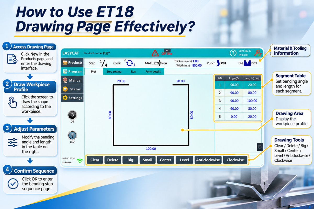
How to Access the ET18 Drawing Page
The controller manual describes the following procedure for entering the graphical drawing interface.
Step 1: Open the Product Library
Start from the controller’s product library interface.
Найдите New icon, which is used to create a new product.
Step 2: Create a New Product
Select the New icon to open the new product interface.
Choose the graphical programming option and use the confirmation button to enter the drawing interface.
Step 3: Check the Drawing Workspace
After entering the ET18 Drawing Page, review the available drawing area and editing tools.
The interface contains several important elements:
- Central workpiece drawing area
- Bending angle and length parameter table
- Drawing adjustment buttons
- Product and material information
- Navigation options for subsequent programming stages
Understanding these elements makes graphical programming easier to manage.
How to Draw a Bending Profile
The ET18 Drawing Page allows operators to create the required workpiece shape by interacting directly with the touchscreen.
The manual instructs users to click the screen and draw the bending part according to the required drawing.
Step 1: Review the Workpiece Drawing
Before entering the profile, identify the required workpiece dimensions and bending angles.
For example, a sheet metal component may contain several straight segments connected by bends.
The intended profile should be established before editing the graphical representation.
Step 2: Create the Workpiece Outline
Use the drawing area to construct the required bending profile.
The example provided in the manual shows an open rectangular profile with multiple bends.
The profile is displayed as connected line segments, allowing operators to see the general shape of the workpiece.
Step 3: Review the Segment Table
The right-hand table displays information under the following headings:
S/N: Segment sequence number.
Angle (°): Bending angle associated with the segment.
Length (mm): Length of the corresponding segment.
These values provide a numerical reference for the graphical profile.
Adjusting Bending Angles and Lengths
One important advantage of the ET18 Drawing Page is the ability to modify the workpiece geometry through its parameter table.
According to the manual, operators can change the angle and length of each bending segment according to actual processing requirements.
Adjusting the Bending Angle
Select the relevant angle value in the segment parameter table and modify it according to the workpiece drawing.
The example interface includes negative angle values, such as -90.00°, which represent the angle convention used in the displayed profile.
Operators should follow the controller’s angle convention rather than assuming that positive and negative values are interchangeable.
Adjusting Segment Length
The Length column displays the dimensions of individual straight segments.
Operators can modify these values to match the required workpiece geometry.
After changing an angle or length, review the displayed profile to confirm that the resulting shape corresponds to the intended component.
Understanding the Drawing Tools
The ET18 Drawing Page includes several visible tools for editing and viewing the workpiece profile.
| Инструмент | Функция |
|---|---|
| Прозрачный | Clears the drawing content |
| Удалить | Deletes selected drawing content |
| Большой | Enlarges the displayed drawing |
| Маленький | Reduces the displayed drawing |
| Center | Centers the drawing in the workspace |
| Уровень | Adjusts the drawing’s displayed orientation |
| Anticlockwise | Rotates the drawing counterclockwise |
| По часовой стрелке | Rotates the drawing clockwise |
These tools help operators inspect and adjust the graphical representation.
The precise effect of each editing command should be confirmed on the controller before modifying an important production program.
Confirming the Bending Step Sequence
After completing the workpiece drawing, the next stage is bending sequence preparation.
According to the ET18 manual, operators should select the confirmation button after editing to enter the step sequence adjustment page.
The bending sequence determines the order in which the programmed bends will be performed.
This is important because an unsuitable sequence can make subsequent bends difficult or create interference between the workpiece and tooling.
Before proceeding, operators should review the proposed sequence against the workpiece geometry and machine configuration.
Once the step sequence has been confirmed and the machine setup has been checked, the program can proceed toward bending operation.
Common Drawing Mistakes to Avoid
When using the ET18 Drawing Page, operators should pay attention to several potential mistakes.
Incorrect segment lengths: Verify every dimension against the original workpiece drawing.
Incorrect bending angle direction: Check the controller’s positive and negative angle conventions.
Incomplete workpiece profile: Review the entire drawing before confirming the program.
Unverified bending sequence: Ensure that the planned order is suitable for the tooling and workpiece geometry.
Accidental drawing modifications: Use editing commands carefully and review the resulting profile after making changes.
Proper verification helps reduce programming errors before production.
Часто задаваемые вопросы (FAQ)
Can the ET18 Drawing Page Create Profiles with Multiple Bends?
Yes. The graphical interface supports workpiece profiles containing multiple bending segments. Operators can review the associated angle and length values in the parameter table.
Does Creating a Drawing Automatically Complete the Bending Program?
No. After completing the drawing, operators must proceed to the bending sequence adjustment page and confirm the step sequence before preparing the machine for operation.
Can the Drawing Page Replace Tooling and Safety Checks?
No. Graphical programming does not eliminate the need to verify tooling compatibility, workpiece clearance, machine setup, and operating conditions.
Заключение
The ET18 Drawing Page provides a practical method for preparing sheet metal bending profiles through graphical programming. By combining touchscreen drawing with adjustable angle and length parameters, the interface helps operators visualize workpiece geometry before bending.
Understanding the drawing tools, segment parameter table, and sequence confirmation process is essential for effective operation.
Operators should carefully review the completed profile, verify its dimensions, and confirm the bending sequence before production.
With proper use of the ET18 Drawing Page, manufacturers can organize graphical bending programs more clearly, reduce avoidable programming mistakes, and improve the consistency of press brake operations.


