


Adequado ESTUN E315P EMC Protection is essential for maintaining stable communication, accurate signal transmission, and reliable CNC controller operation in an industrial environment. Press brakes contain components such as motors, servo drives, VFDs, relays, and contactors that may generate electromagnetic interference during operation.
Without appropriate EMC measures, electrical noise may affect encoder feedback, I/O signals, communication, and other sensitive control circuits. In this guide, we will explain the main ESTUN E315P EMC Protection measures, including grounding, cable routing, shielding, interference control, installation requirements, and flyback diode protection for relay circuits.
What Is ESTUN E315P EMC Protection?
Adequado ESTUN E315P EMC Protection helps the CNC controller operate reliably in an industrial environment where motors, servo drives, VFDs, relays, and contactors may generate electromagnetic interference.
Electrical noise can affect encoder feedback, I/O signals, and communication. Therefore, effective EMC protection requires a combination of proper grounding, cable routing, shielding, and interference suppression.
The main measures include:
- Low-impedance grounding
- Separation of power and signal cables
- Correct shield connections
- Proper encoder cable routing
- Reliable cabinet grounding
- Suppression of inductive loads
Use Low-Impedance Grounding
Reliable grounding is one of the basic requirements for ESTUN E315P EMC Protection.
The controller chassis and other metal components should be securely connected to protective earth according to the machine electrical design. Grounding connections should provide low impedance, good conductivity, and reliable mechanical contact.
According to the E315P requirements, the chassis grounding impedance should be ≤0.3 Ω.
Loose or poor grounding connections may reduce EMC performance and increase the influence of electrical noise.
How to Route E315P Cables Correctly?
Cable routing has a major influence on electromagnetic compatibility. High-power cables and sensitive signal cables should be separated whenever possible.
Separate Power and Signal Cables
Different cable types should be routed separately, especially:
- High-voltage cables
- Motor and power cables
- Cabos do codificador
- Signal and I/O cables
Avoid running signal and encoder cables parallel to high-current wiring for long distances.
If different cable types must cross, minimize the distance over which they remain close together.
Protect Encoder Cables
Encoder signals are sensitive to electrical interference because they provide position feedback to the controller.
Encoder cables should therefore be kept away from motors, VFDs, servo drive power cables, and other strong interference sources.
Shielded encoder cables should be used according to the E315P installation requirements.
How to Connect Shielded Cables?
Correct cable shielding helps prevent electromagnetic interference from reaching sensitive control signals.
Ensure Reliable Shield Grounding
Cable shields should be securely connected to protective earth according to the specified grounding arrangement.
The shield-to-earth connection should provide a large contact area and low impedance.
Long or loose shield connections should be avoided because they can reduce shielding effectiveness.
Shield Both Ends When Required
For encoder and other specified shielded cables, both ends should normally be grounded according to the E315P installation requirements.
If a significant potential difference exists between the grounding points, the grounding arrangement should be evaluated according to the machine electrical design.
What Are Common EMC Interference Sources?
Several components commonly installed in press brake electrical systems can generate electromagnetic interference.
Contactors and Relays
Contactors and relays contain inductive coils that can generate electrical transients when switched on or off.
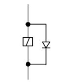
Appropriate suppression measures and cable separation help prevent these transients from affecting control circuits.
VFDs and Servo Drives
VFDs and servo drives use high-frequency switching and can generate significant electrical noise.
Sensitive signal and encoder cables should be kept away from their power cables.
Motors
Motors and motor power cables can also introduce interference into nearby circuits.
Motor wiring should therefore be separated from CNC communication, encoder, and control wiring whenever possible.
Understanding EMC Interference Coupling
Electrical interference can reach the E315P through several different paths.
Direct Electrical Coupling
This occurs when different devices share electrical paths, such as common power or grounding connections.
Electrical disturbances generated by one device may then influence another device.
Capacitive Coupling
Capacitive coupling can occur when power and signal cables run close together, especially over long parallel distances.
Proper cable separation helps reduce this effect.
Inductive Coupling
Changing current creates magnetic fields that can induce unwanted signals in nearby conductors.
Typical sources include transformers, relays, contactors, and high-current wiring.
Radiative Coupling
Electromagnetic fields can also radiate through the surrounding environment and induce unwanted voltages in nearby wiring.
Proper shielding and grounding help reduce this type of interference.
How to Improve E315P EMC Installation?
Good EMC performance depends on the overall electrical installation rather than one individual component.
Ground the Controller and Cabinet
The controller chassis and electrical cabinet should be connected reliably to protective earth.
Grounding points should be clean, secure, and designed to maintain low impedance.
Use Separate 24V Power Supplies
According to the E315P installation recommendations, two isolated 24V DC power supplies can be used:
- One for the controller and internal circuits
- One for the I/O terminals
This arrangement helps isolate the controller electronics from disturbances generated by external I/O circuits.
Keep Sensitive Cables Away From Interference
Encoder, communication, and signal cables should be routed away from VFDs, servo drives, motors, contactors, and high-current conductors.
Combining proper cable separation with shielding and grounding provides better EMC performance.
Why Add Flyback Diodes to Relays?
Relay coils are inductive loads. When a DC relay is switched off, the collapsing magnetic field can generate a high-voltage transient.
A properly connected flyback diode provides a path for this stored energy and helps suppress the voltage spike.
Using appropriate relay suppression can help:
- Reduce electrical transients
- Reduce electromagnetic interference
- Protect control outputs
- Improve system reliability
The diode polarity and connection must follow the electrical design of the DC relay circuit.
Image summary: A flyback diode connected across a DC relay coil suppresses voltage spikes when the relay is switched off.
Best Practices for ESTUN E315P EMC Protection
For reliable ESTUN E315P EMC Protection, technicians should combine several measures rather than relying on a single solution.
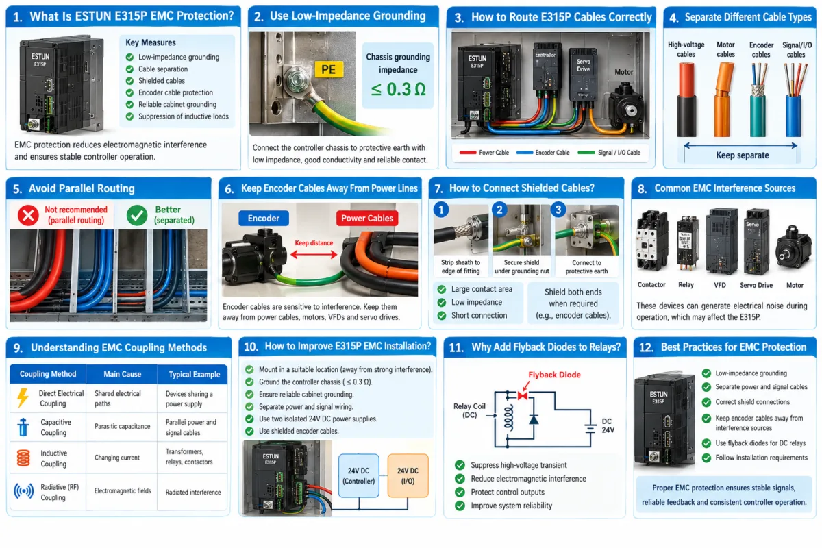
Use low-impedance grounding, keep power and signal cables separated, connect cable shields correctly, and protect sensitive encoder wiring from strong interference sources. VFDs, servo drives, motors, relays, and contactors should always be considered when planning the electrical cabinet layout.
Proper EMC installation helps maintain stable signal transmission, reliable encoder feedback, and consistent E315P controller operation.
Perguntas frequentes (FAQ)
Why Should Power and Signal Cables Be Separated?
Power cables can generate electromagnetic fields that interfere with nearby signal wiring. Long parallel runs between power and signal cables can increase capacitive and inductive coupling.
What Is a Flyback Diode Used For?
A flyback diode is used with suitable DC relay coils to suppress the high-voltage transient generated when the relay is switched off.
What Should I Check If EMC Problems Occur?
If interference-related problems are suspected, check the grounding connections, cable routing, shield connections, encoder wiring, power supply arrangement, and proximity of signal cables to strong interference sources.
VFDs, servo drives, motors, contactors, and relays should receive particular attention during troubleshooting.
Conclusão
Proper ESTUN E315P EMC Protection is important for maintaining stable communication, accurate encoder feedback, and reliable Dobradeira controller operation. Effective protection depends on the entire electrical installation rather than a single grounding or shielding measure.
Technicians should use low-impedance grounding, separate power and signal cables, connect cable shields correctly, and keep sensitive encoder wiring away from strong interference sources. Appropriate suppression measures, such as flyback diodes for suitable DC relay coils, can further reduce electrical transients.
By following the recommended ESTUN E315P EMC Protection practices, users can reduce electromagnetic interference and provide a more stable electrical environment for the E315P control system.


