


This comprehensive guide explores Pipe Bending Axes Analysis in depth, explaining how each axis—Y, B, C, A, Z, and X—contributes to bending precision, machine efficiency, and production reliability. Learn how optimizing multi-axis interaction enhances fabrication outcomes and reduces cycle time.
Pipe Bending Axes Analysis: Why It Has Become Essential in Modern Fabrication
As manufacturing transitions toward automation and high-precision production, Pipe Bending Axes Analysis has emerged as one of the most valuable engineering approaches for ensuring consistent bending quality and achieving efficient production flow. Multi-axis pipe bending machines are no longer simple mechanical devices; they have become complex electromechanical systems that rely on synchronized axis interaction, servo-controlled feedback loops, and adaptive parameters tailored to different materials.
In this context, understanding the individual roles of each axis, as well as the collective dynamics between axes, empowers operators and engineers to pursue greater accuracy, minimize material waste, shorten cycle time, and maintain long-term machine stability. This article provides a thoroughly expanded and highly detailed analysis of each axis, its operational characteristics, and the engineering principles behind precise bending.
Expanded Axis Analysis with Technical Depth
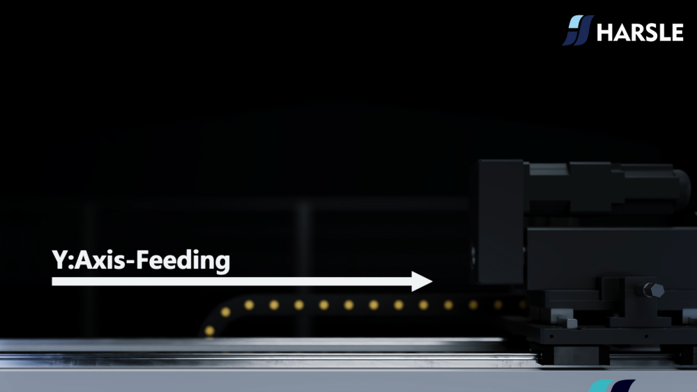
1. Y Axis – Feeding
In Pipe Bending Axes Analysis, the Y axis acts as the starting point of all subsequent bending operations, since the exact feed length dictates the positioning of every bend in the sequence. An error in Y-axis positioning—even as small as a few tenths of a millimeter—can accumulate across multiple bends and result in dimensional deviations, assembly issues, or scrapped material.
Because of this, the feed system must maintain strict control over speed, torque, clamp grip, and positional feedback.
Expanded Technical Considerations
- Feed Speed Behavior
Higher feed speeds allow for fast cycles but may generate vibrations or micro-slippage along the pipe surface. Robust control loops are needed to compensate. - Servo vs. Hydraulic Feeding
Servo feeding ensures high repeatability, while hydraulic feeding provides greater pushing force—selecting the right system depends on pipe diameter and wall thickness. - Sensor Integration
Laser and encoder-based feed sensors significantly improve accuracy by providing real-time feedback, enhancing positioning precision with automatic correction. - Material Surface Interaction
Metals like stainless steel require stable clamping pressures to avoid surface dents, making clamping force calibration an essential part of feed accuracy.
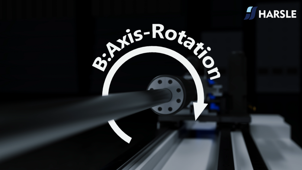
2. B Axis – Rotation
The B axis determines how the pipe is oriented before bending occurs, and its rotational accuracy directly influences the machine’s ability to produce parts with multidirectional geometry, such as automotive exhausts, HVAC tubes, and hydraulic lines.
Expanded Technical Considerations
- Rotational Inertia Compensation
Larger or heavier pipes have greater inertia, requiring refined acceleration and deceleration control to prevent overshoot. - Multi-Axis Synchronization
The B axis must operate in perfect harmony with the Y and C axes to maintain geometric integrity throughout consecutive bends. - Encoder Resolution
High-resolution encoders allow for precise angular correction, enabling complex bending patterns that would be impossible with low-precision feedback devices. - Fixture and Clamp Design
The rotational fixture must prevent pipe slippage during high-torque rotations to keep angular accuracy stable.
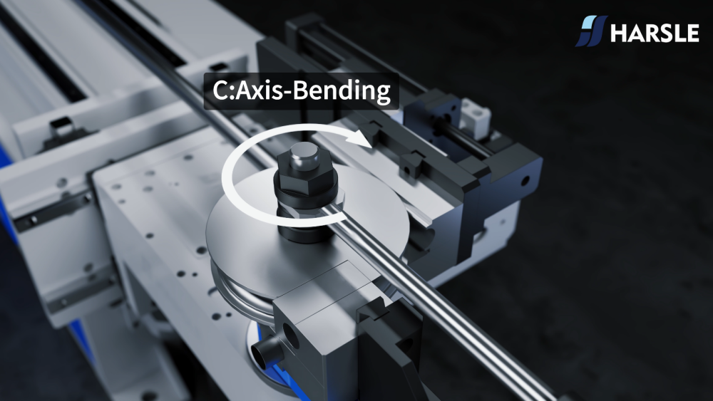
3. C Axis – Bending
The C axis is the heart of the Pipe Bending Axes Analysis framework. It applies force to bend the pipe, and the quality of this action defines the final geometry, surface integrity, and structural consistency of the finished part.

Expanded Technical Considerations
- Force Distribution & Radius Control
The machine must apply a consistent bending force across the pipe to avoid flattening or cracking, especially when forming tight radii. - Springback Prediction Models
Modern systems use material databases to predict springback behavior, allowing the machine to automatically apply compensation. - Mandrel and Wiper Die Optimization
Selecting the correct mandrel type—plug, form, or ball mandrel—dramatically improves the internal surface quality and prevents wrinkling. - Adaptive Bending Algorithms
Advanced control systems analyze bending resistance in real time, adjusting torque or angle to maintain the programmed geometry.
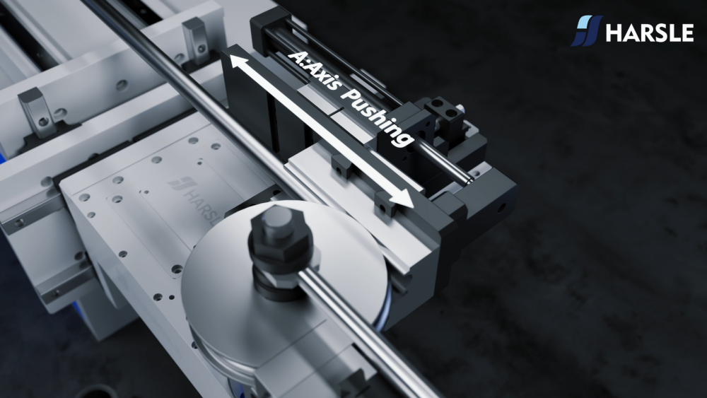
4. A Axis – Pushing
The A axis provides additional longitudinal support and ensures the pipe remains in the correct alignment during extended bends or when working with large, heavy, or long pipes.
Expanded Technical Considerations
- Long-Stroke Stability
For long pipes, pushing must remain stable over prolonged travel distances to avoid sagging or shifting. - Torque & Force Monitoring
Sensors detect abnormal resistance, ensuring that the pipe does not deform or collide with tooling. - Integration With Y Axis
In high-precision bending sequences, the Y and A axes must operate cohesively to guarantee proper alignment and positioning.
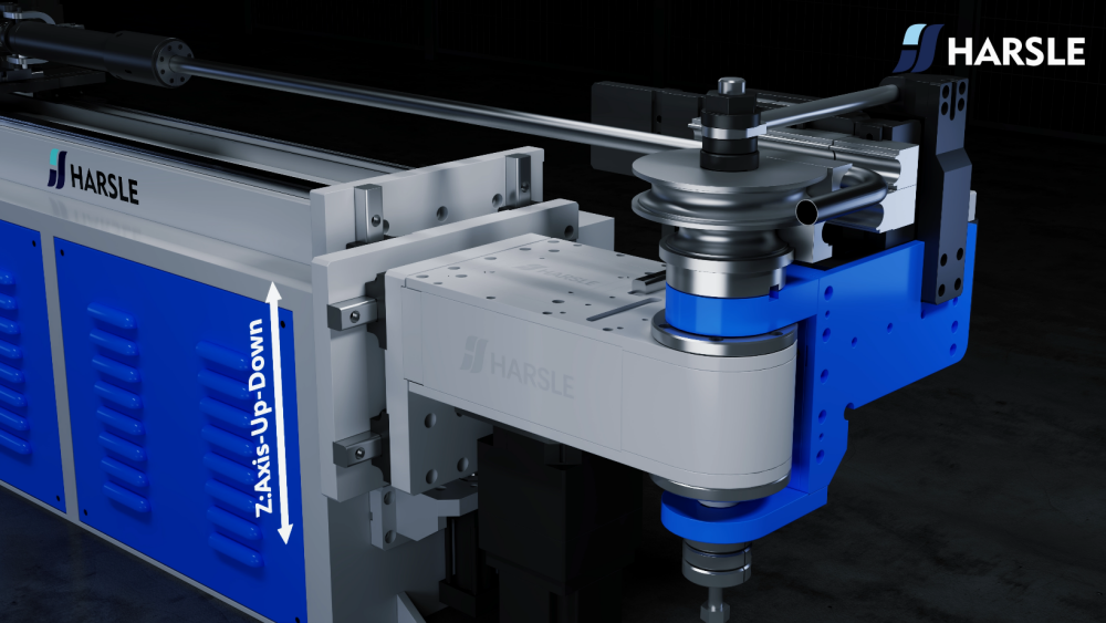
5. Z Axis – Vertical Movement
The Z axis adjusts vertical clearance, enabling operators to switch between tooling, alter bending geometries, and create space for multi-layer bending operations.
Expanded Technical Considerations
- High-Load Lifting Capability
The Z axis must maintain rigidity and stability under heavy loads, especially when handling large dies. - Vertical Repeatability
Accurate height control ensures that every bend begins with a consistent tooling setup. - Safety and Clearance Functions
Vertical height adjustment protects the machine from collisions during complex multi-bend cycles.
6. X Axis – Horizontal Movement
The X axis ensures lateral alignment during bending, especially critical when producing multi-plane or spatially complex parts.

Expanded Technical Considerations
- Cross-Positioning Precision
High-precision linear rails and ball screws keep horizontal travel smooth and consistent. - Complex Geometric Compensation
Lateral compensation is often needed to accommodate springback or material elasticity. - Closed-Loop Feedback
Servo-driven horizontal positioning ensures accurate development of multi-directional parts.
How Pipe Bending Axes Analysis Enhances Efficiency
Applying systematic Pipe Bending Axes Analysis enables operators to identify weak points in production, adjust axis-interaction parameters, optimize overlapping operations, and reduce unnecessary idle time between bends. With a strategic axis analysis approach, manufacturers can:
- Reduce cycle time
- Increase machine utilization
- Improve product consistency
- Lower scrap rates
- Extend machine lifespan
Ultimately, axis-level optimization yields a more predictable and stable bending environment.
Ongoing Challenges and Practical Solutions
Even with advanced Pipe Bending Axes Analysis, fabrication teams still face real-world issues such as:
- Material hardness variation
- Temperature-dependent springback
- Tool wear and die misalignment
- Sensor calibration drift
- Operator inconsistency
Solutions typically involve preventive maintenance, periodic calibration, and the integration of monitoring systems capable of capturing anomalies before they affect production.
Conclusion: Future Trends in Pipe Bending Axes Analysis
As machine intelligence evolves, Pipe Bending Axes Analysis is expected to incorporate AI-driven predictive adjustments, automated springback calculation, real-time force mapping, and self-optimizing bending algorithms. These advancements will enable bending machines to make autonomous decisions, significantly improve accuracy, and reduce operational costs.
By embracing Pipe Bending Axes Analysis as a core practice, manufacturers can position themselves for higher productivity, enhanced product quality, and long-term competitive strength in the fabrication industry.


