


When exploring advanced press brake controllers, understanding the DELEM DA-69S Machine Mode is crucial for optimizing your metalworking processes. If you’re searching for insights on how this powerful system can enhance your operations, you’re in the right place.
In this article, I’ll delve into the key features of the DELEM DA-69S Machine Mode, explaining its functionalities and benefits. Whether you’re new to using press brake controllers or looking to improve your current setup, this guide will provide you with the knowledge needed to fully exploit this advanced technology for your specific needs.
Introduction to DELEM DA-69S Machine Mode
The DELEM DA-69S is known for its robust features that cater to intricate metalworking tasks. Its user-friendly interface allows operators to smoothly transition between different modes and functionalities, opening up numerous possibilities for custom operations.
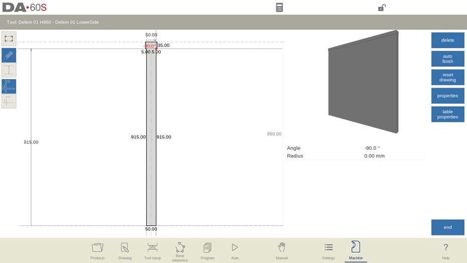
By tapping the navigation button Machine the control is switched to Machine mode.
The DELEM DA-69S Machine Mode allows users to configure machine settings and characteristics that affect its operation. Accessed via the navigation panel, settings are organized into tabs for easy navigation. Users can tap and drag these tabs vertically to view and adjust all available options.

Programming of Punches and Dies
Punch Programming
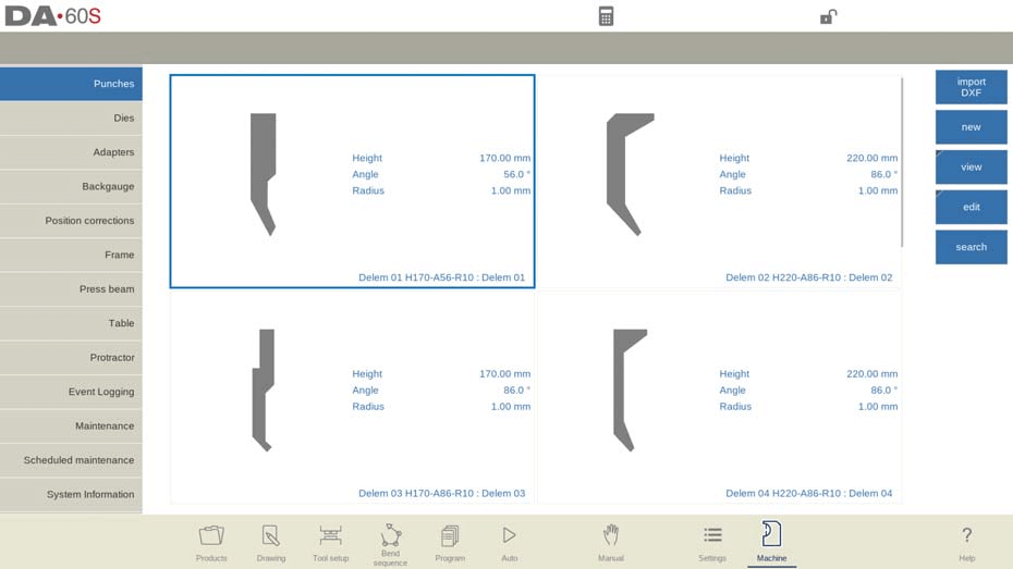
In the DELEM DA-69S Machine Mode, punches can be effectively programmed, allowing for the addition of new punches, as well as the editing, copying, renaming, and deletion of existing ones.
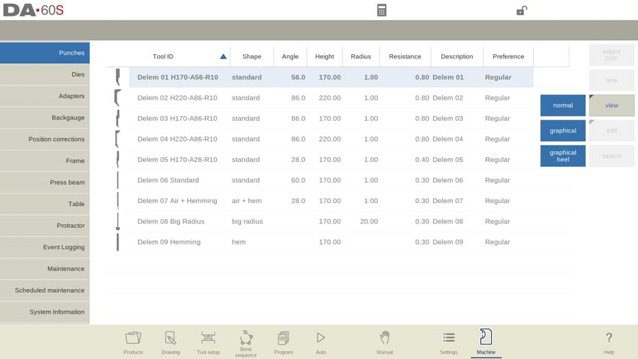
View
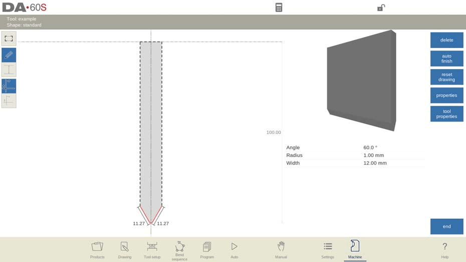
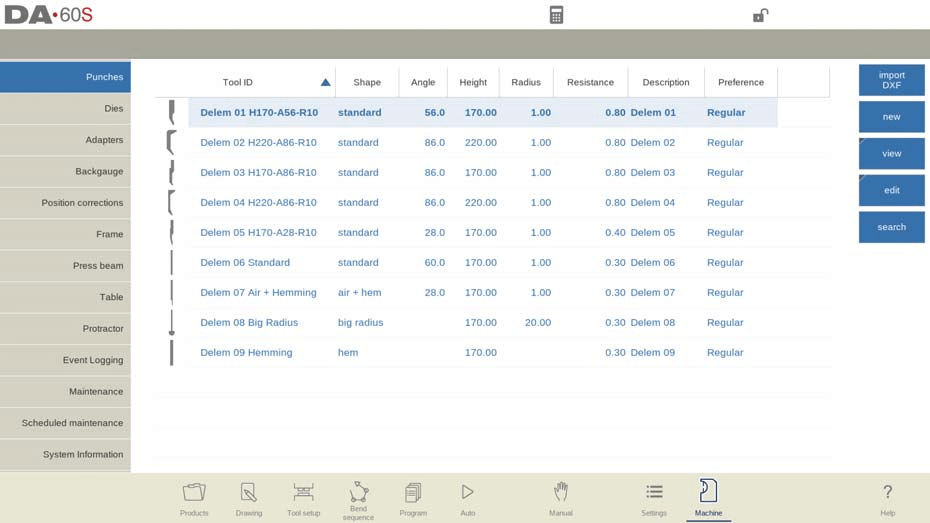
In DELEM DA-69S Machine Mode, the main page displays available punches with various viewing options. Users can choose from Normal, Graphical, and Graphical Heel views to see tool geometry and properties, enhancing their operational overview.
- Graphical directory
- Graphical directory punches with heels

Create a new punch
In the DELEM DA-69S Machine Mode, creating a new punch involves selecting “New” in the library and programming the punch shape and unique ID.
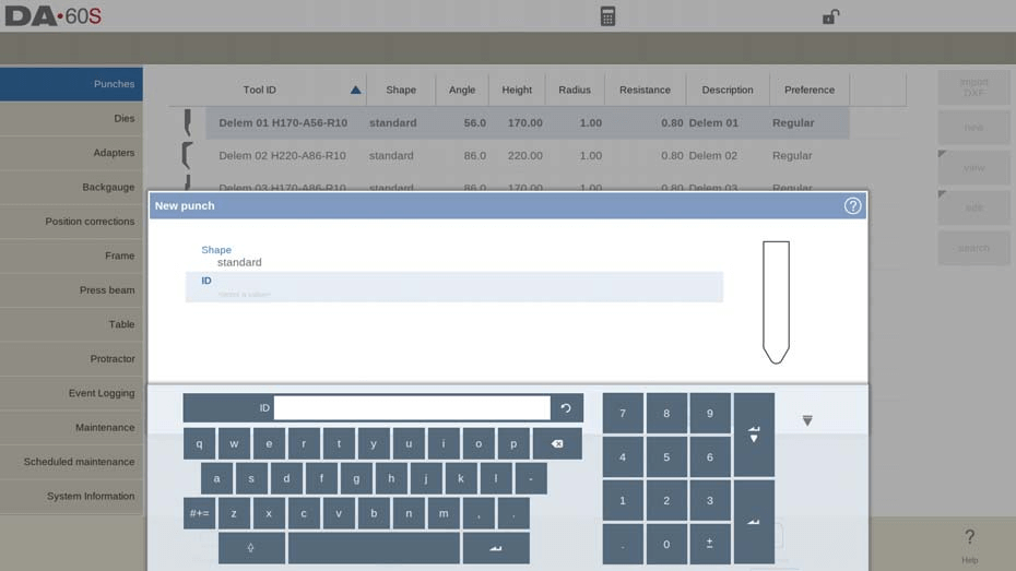
Options include Standard, Hem Bend, Air + Hem Bend, and Big Radius punch shapes. The ID can be up to 25 alphanumeric characters. After setting the ID, configure the tool data parameters.
With the DXF import option, punch shapes can also be loaded directly.
- Standard punch
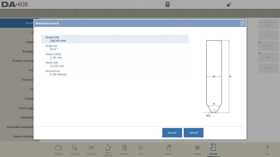
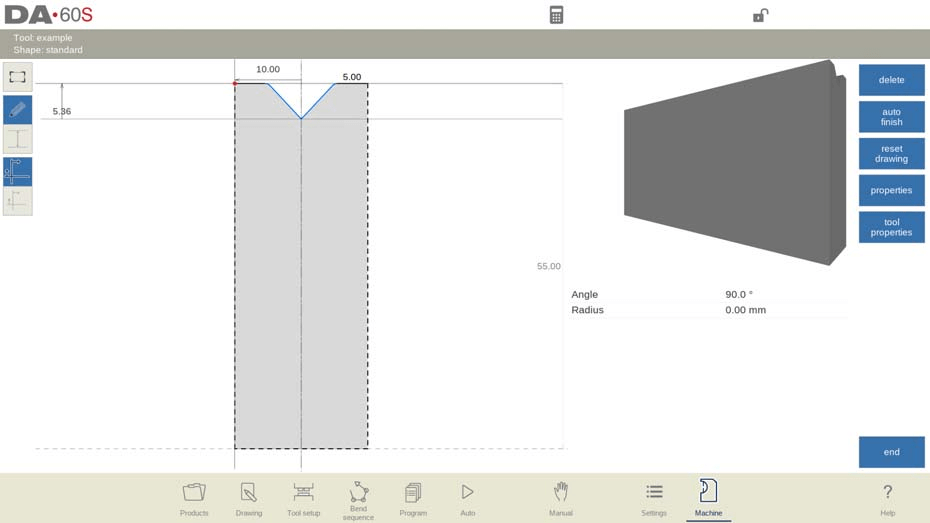
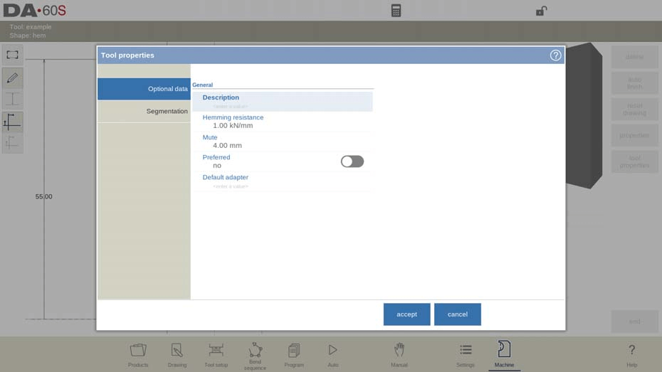
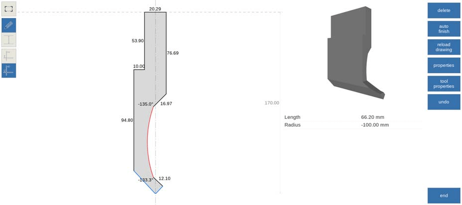
In DELEM DA-69S Machine Mode, punch programming involves defining critical parameters: height for bend depth calculations, tip angle, radius for the inner bend, width, and maximum resistance. Correct screen orientation ensures accurate tool placement. Use the drawing facilities for tool profile creation and modifications, enabling features like line deletion and automatic outline finishing.
Customize tool properties, including description, resistance, support type, preferred tool status, and default adapter setting, for efficient operation.
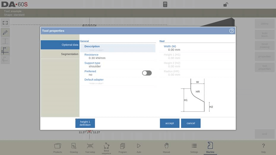
Support type:
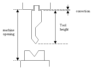
Support type adjustment is essential for maintaining accuracy with differently mounted punches. The system differentiates between ‘head mounted’ and ‘shoulder mounted’ settings to account for potential inaccuracies in tool height affecting the Y-axis position.

By default, ‘shoulder mounted’ uses the standard tool height for Y-axis calculations. However, when ‘head mounted’ is selected, the system applies a correction to ensure precise Y-axis computation.
Heel dimensions are also specified without affecting tool height. Editing tools allows for precise adjustments using the drawing functionalities, optimizing performance in metalworking tasks.
Edit punch:
To edit an existing tool, tap the tool in the library. The tool appears on the screen and can be edited with the drawing facilities.
- Hem bend punch
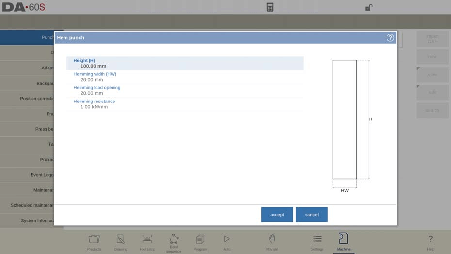
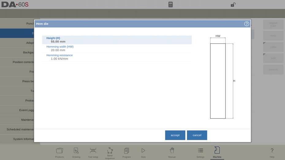
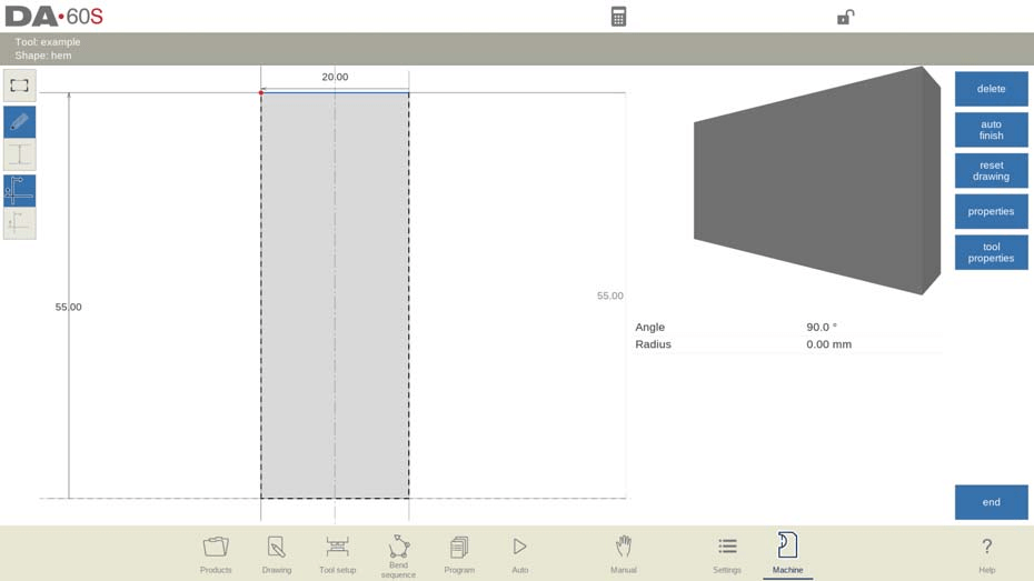
In DELEM DA-69S Machine Mode, configuring a hem bend punch requires key parameters: tool height for bend depth, hemming width, and an opening position considering double sheet thickness. Additionally, set the hemming resistance for safe force limits. Use drawing tools to outline the tool profile by adjusting angle values and line lengths.
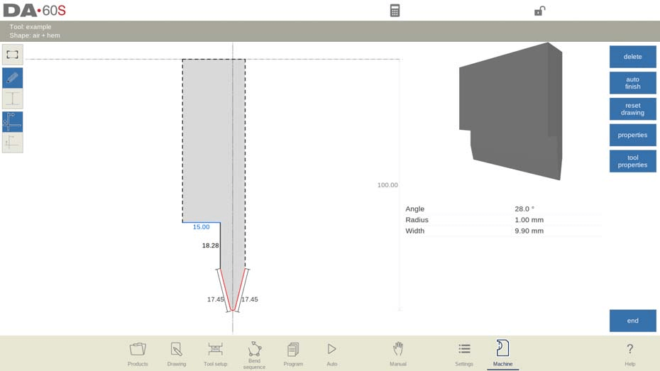
- Air + hem bend punch

In DELEM DA-69S Machine Mode, configuring the “Air + hem bend punch” involves specifying key parameters like tool height, which affects bend depth, and the punch tip angle and radius. It’s essential to define the tool’s width, maximum resistance, and specific hemming attributes—height, width, load opening, and resistance—to ensure precise bending.

These settings, taking into account twice the sheet thickness for accurate positioning, allow for the creation of detailed tool drawings using angle and line length inputs. This process ensures efficient and accurate hem bending operations.
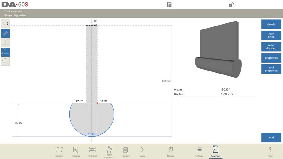
- Big radius punch

Setting up a big radius punch involves defining tool height, punch tip radius, radius height, resistance, and top width. These parameters aid in bend depth calculations. Users can create tool drawings using angles and line lengths, utilizing Touch drawing tools for precision, similar to product drawing methods.
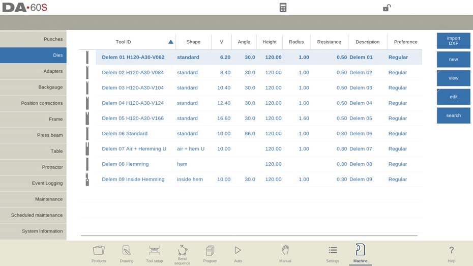
Die Programming
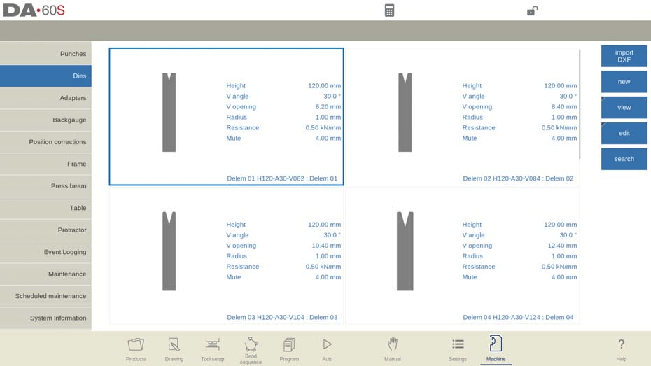
In this tab, the dies used in the machine can be programmed. New dies can be added; existing dies can be edited, copied, renamed and deleted.
View
In the DELEM DA-69S Machine Mode, the main page features a die list with a View function allowing selection between Normal and Graphical views. The Graphical view showcases tool geometry and main properties.
- Graphical directory
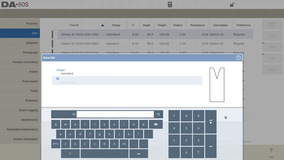
Create a new die
In the DELEM DA-69S Machine Mode, creating a new die starts by selecting “New” in the library.
You can program and draw the die’s profile by choosing from various basic shapes, such as standard, hem bend, multi-V, and specialized dies like Doorframe Hem Bend or Wingbend Die, each catering to specific functions like air bending or hemming.
Assign a unique ID (up to 25 alphanumeric characters) to identify the tool. After setting the shape and ID, proceed with the tool data parameters.
The optional DXF import feature facilitates precise die shape loading, optimizing design efficiency.
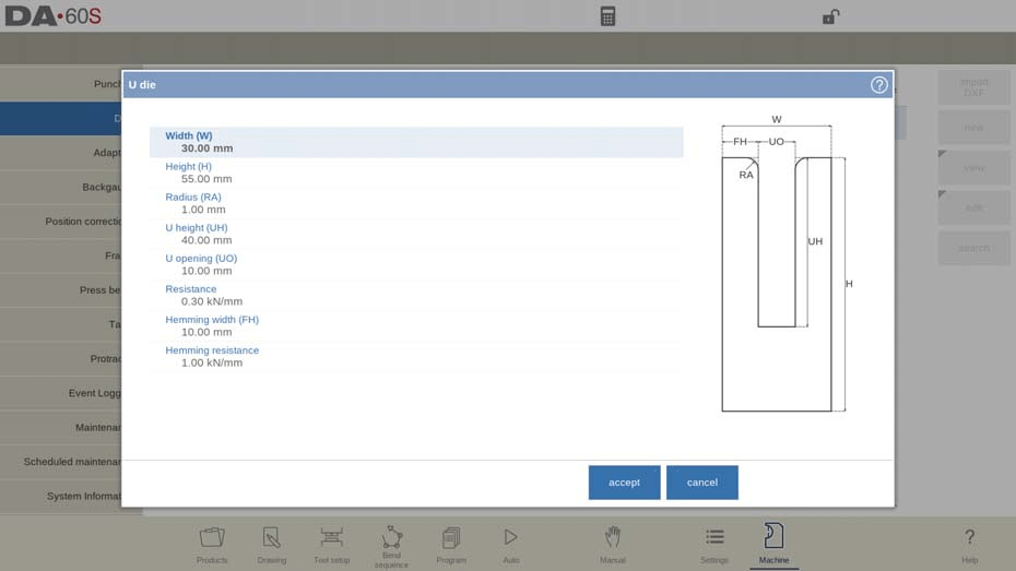
- Standard die
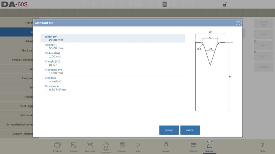
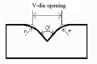
In DELEM DA-69S Machine Mode, programming a standard die involves setting key parameters such as width, height, radius, V angle, and V opening. The V-opening is the distance between the touching lines crossing.
These factors are crucial for determining bend depth and tooling efficiency. The die can have different V bottom types, including sharp, round, or flat, and its orientation on the machine ensures optimal force application.
Drawing features enable precise tool profiles, with options to edit lines, change heights, and refine tool outlines.
Tool properties like resistance, muting distance, and preferred settings enhance functionality and streamline setups.
A default adapter can be assigned for regular use, optimizing efficiency.
Edit die:
To edit an existing tool, tap the tool in the library. The tool appears on the screen and can be edited with the drawing facilities. A round upper side can be created by dragging the end of the surface, connected to the radius, downwards.
- Hem bend die
In DELEM DA-69S Machine Mode, setting up a hem bend die requires inputting the tool height for accurate bend depth calculations, specifying the hemming width, and defining the maximum hemming resistance.
After entering these parameters, use angle and line length inputs or Touch drawing tools to create the tool profile, enhancing precision and efficiency.
- Inside hem bend die
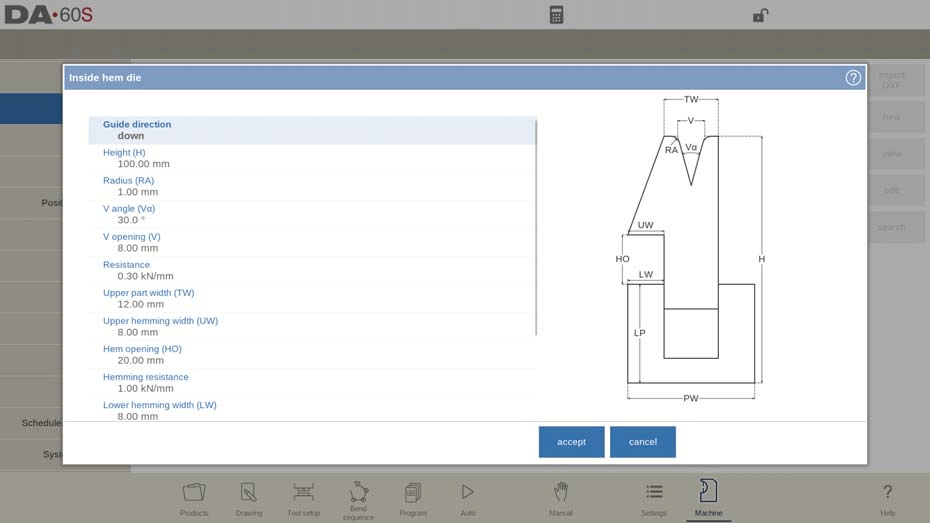
- Height: The total height is crucial as it is used in bend depth calculations.
- Radius: Set the radius of the edges of the V-opening to align with design requirements.
- V Angle: Define the die’s angle for correct bending alignment.
- V Opening: Adjust the opening for adequate material insertion and bending.
- V Bottom: Choose between ‘Standard’, ‘Round’, or ‘Flat’ bottoms based on your application needs.
- Resistance: Ensure the specified maximum allowable force does not exceed tool capacity during operation and hemming.
- Upper and Lower Die Dimensions
- Measure and input the width of the upper and lower die parts to ensure they match the product’s technical requirements.
- Set upper and lower hemming widths to guide the hemming action precisely.
- Hem Opening and Resistance
- Hem Opening: Define the opening height for product placement.
- Hemming Resistance: Set the resistance level for force management during hemming.
- Inside Hemming Die Type
- Spring Opened: Automatically sets to an open position, facilitating pre-bend and hem-bend.
- Open & Locked: Locked high position for normal operations and requires adjustments for hemming.
- Normally Closed: Defaults to a low position, requiring activation for hemming.
- Adapt Decompression: Determine whether to add the hem opening value to the decompression distance based on your bending requirements.
- yes => added for both air bends and hem bends.
- air bend => added for air bends only (only available for spring opened hemming dies).
After entering these typical values you can create the tool drawing with the drawing facilities.
Drawing and DXF Import (only available when DXF option has been installed)
Drawing a tool profile is done by entering angle values and line length values. Also the Touch drawing tools are available as with the product drawing method. Optional DXF import for tool shapes streamlines setup; ensure DXF use consistent layer naming for automatic tool type selection.
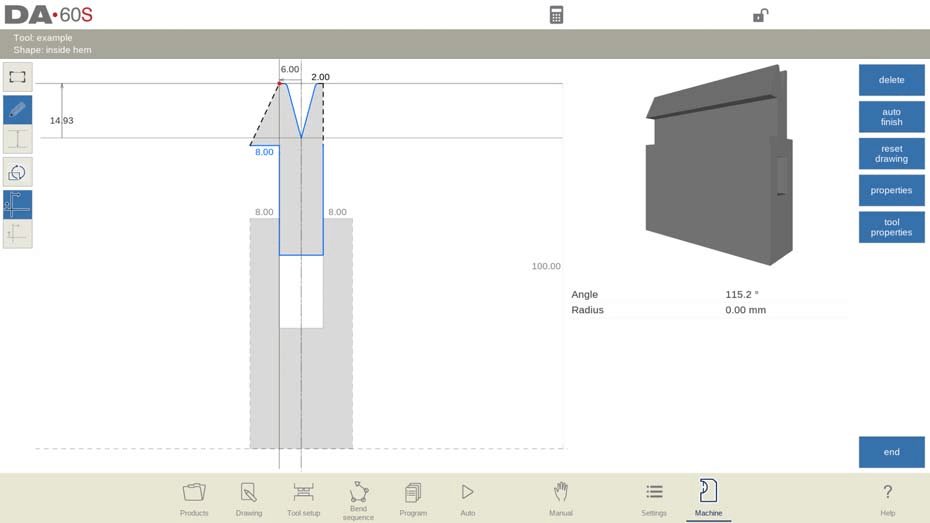
By following these streamlined steps in the DELEM DA-69S Machine Mode, operators can efficiently program and operate inside hem bend dies to produce high-quality bent products. Understanding these parameters ensures you leverage the full potential of your press brake system for optimal productivity and accuracy.
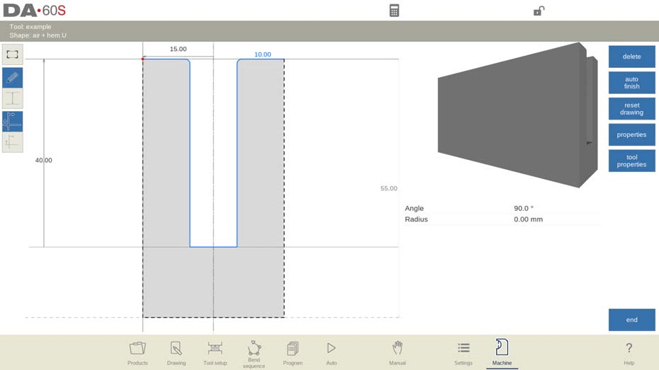
- Air + hem bend U die
To program an Air + Hem Bend U die in the DELEM DA-69S Machine Mode, input the tool’s width and total height for bend depth accuracy. Specify the U-opening’s radius, height, and width. Set the maximum resistance for the tool and hemming, with appropriate hemming width for support.
Use drawing facilities to sketch the tool profile by entering angle and line lengths. Utilize Touch drawing tools for intuitive design, enhancing precision and efficiency in DELEM DA-69S Machine Mode operations.
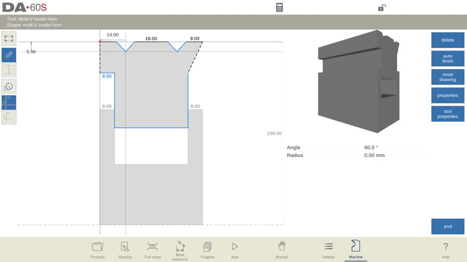
- Multi V die
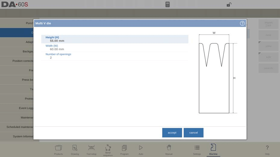
To program a Multi V die in the DELEM DA-69S Machine Mode, start by setting the tool’s height, crucial for bend depth accuracy.
Specify the tool’s width and the number of V or U openings. Each opening can be individually configured with properties like type, edge radius, and V angle. Define the V bottom type as Standard, Round, or Flat, and set the resistance for each opening if needed.
Leverage the drawing tools within DELEM DA-69S Machine Mode to create detailed tool profiles using angles and line lengths. This setup maximizes precision and efficiency in your metalworking operations.

- Vario V die (only available if a Vario-V system is present)
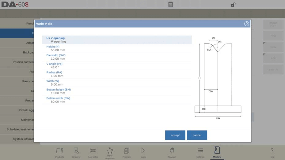
- Height: Total tool height.
- Die Width: Represents half the minimum V-opening, crucial for die positioning.
- V angle: Half of the V angle of the die.
- Radius: The radius of the edges of the U or V opening.
- Width: The width of the V angle of a single Vario V side (i.e. half of the minimum V-opening).
- Bottom Dimensions: Ensure stability with accurate bottom height and width.
Tool Drawing
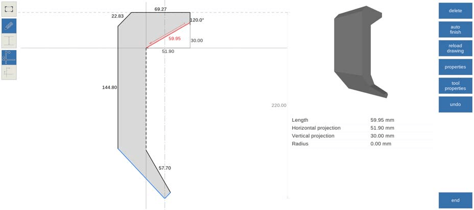
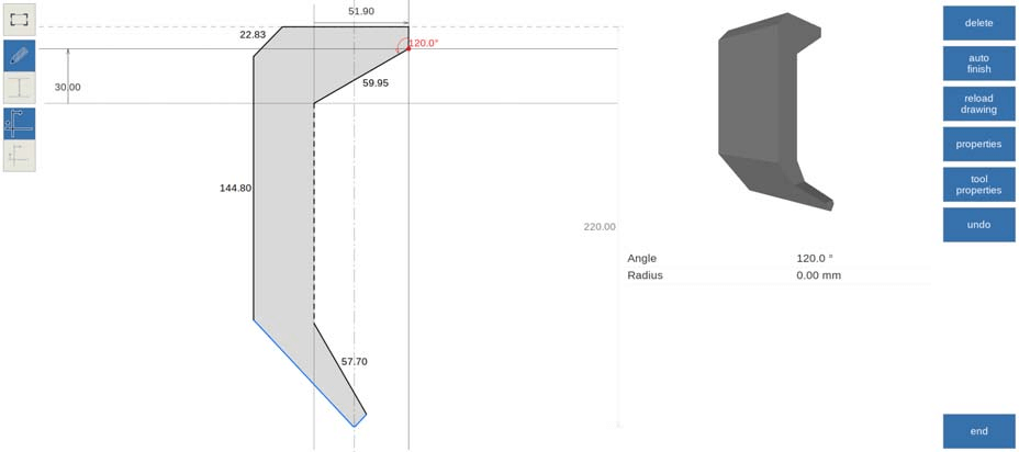
Utilize drawing facilities to create precise tool profiles by entering angle and line lengths.

Tool Properties:
- Description: Assign a recognizable name for easy library access.
- Resistance: Monitor maximum force to maintain tool integrity.
- Adjustments: Set mute distances and V axis offset for calibration accuracy.
- Positions: Configure discrete positions and steps for precise adjustments.
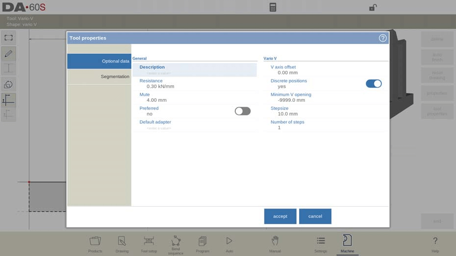
DXF Import: For those with DXF capability, ensure lower die body layers are correctly set for easy tool integration.
- Multi-V inside hem die

- Height (H): This determines the total height crucial for bend depth calculations.
- Upper Part Width (TW) and Lower Part Width (PW): These define the widths of the upper and lower segments of the die.
- Number of openings: Number of V or U openings.
- Hem Angle (Ha): The angle necessary for the hemming unit operation.
- Hemming Specifics
- Upper Hemming Width (UW) and Lower Hemming Width (LW): These widths are essential for the effective hemming action on both the upper and lower parts.
- Hem Opening (HO): Important for placing products with hem bends.
- Hemming resistance: Maximum allowable force on the tool during hemming.
- Lower hemming width (LW): The width of the segment in the lower part of the die used for the hemming action.
- Lower part width (PW): The width of the lower part of the die.
- Lower part height (LP): The height of the lower part of the die.
- Inside hemming die type
- Spring Opened: Springs push the die up initially. Pre-bend and hem-bend operations consider the sheet thickness.
- Open & Locked: Requires unlocking for hemming.
- Normally Closed: Starts in a low position for bending, needs activation for hemming.
- Decompression Settings: Determines if hem openings add to decompression distance, with options for both air and hem bends.
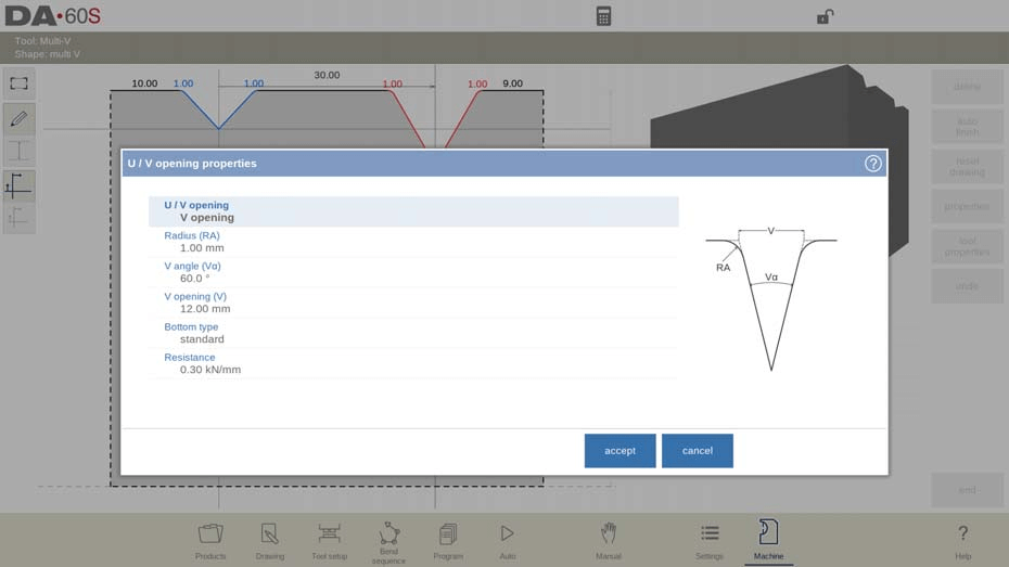
- U/V Opening Properties
- Define number, radius, angle, and specific resistance for each V or U opening.
- V Bottom Types: Options include standard, round, or flat.
- Tool Drawing and Import
- Create tool drawings using line and angle inputs, or import shapes via DXF if installed.
- For DXF imports, ensure the die’s body is in layer 0 and the moving part in another layer, preferably named ‘inside hem.’ Both parts in the DXF need to be closed contours.
- Doorframe hem die
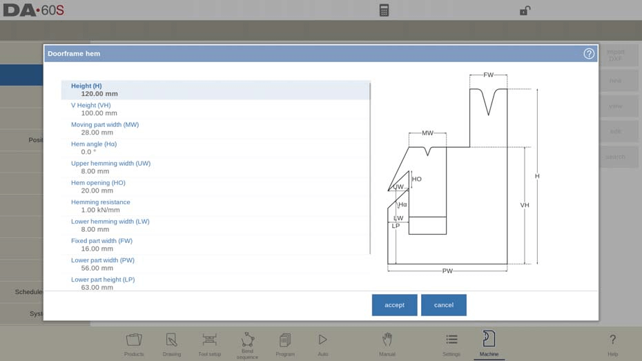
To effectively use the doorframe hem die in DELEM DA-69S Machine Mode, focus on core setup parameters and operations. Key measurements such as tool height (H), V Height (VH), and Moving part width (MW) are critical for accurate bending and hemming. The Hem angle, Upper and Lower hemming widths influence hem quality.
Inside hemming die type
Inside hemming dies offer modes like Spring Opened for adaptive hemming, Open & Locked requiring manual unlocking, and Normally Closed needing activation for hemming.
Adapt decompression
Adapt decompression settings based on bending needs, ensuring compatibility with air bends or hem bends, especially for spring opened dies:
no => not added at all.
yes => added for both air bends and hem bends.
air bend => added for air bends only (only available for spring opened hemming dies).
U / V opening properties
Customize the V opening properties, including Radius, V angle, and V bottom type, to suit specific tasks. Each U or V opening’s properties can be programmed. Tool resistance can be overall or specifically programmed.
DXF import (only available when DXF option has been installed)
Utilize drawing functions and the optional DXF import, ensuring correct layer setups for seamless integration.

- Wingbend die
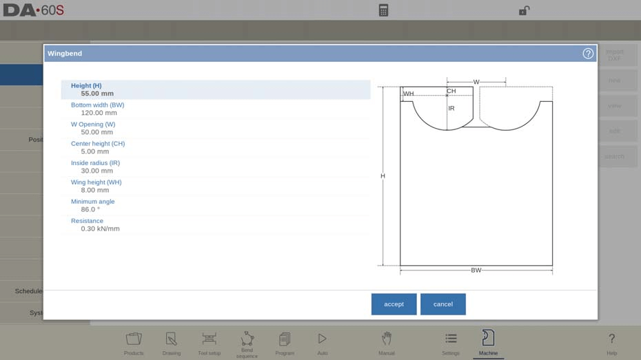
- Height (H): This is the total height of the tool, including any extended wings.
- Bottom Width (BW): This defines the width of the tool for programming.
- W Opening (W): The distance between the rotation points, crucial for fitting and alignment.
- Center Height (CH): The height of the wing above the inner rotation point
- Inside Radius (IR): The radius of the wing measured from its inner rotation point
- Wing Height (WH): Part of the tool’s height, representing how much of the wing is involved in the bending process.
- Minimum Angle and Resistance: Defines the smallest angle achievable and the maximum force allowable on the tool, respectively.
- Wingbend Properties:
- Width (W) and Gap (G): These determine the distance between rotation points and between wings, respectively.
- Center height (CH): Height of the wing above the inner rotation point.
- Inside radius (IR): Radius of the wing from its inner rotation point.
- Wing Width (WW) and Height (WH): These specify the size of the wing, crucial for ensuring proper tool configuration.
- Bottom Height (BH): Indicates the middle part’s height, representing the V-opening’s depth.
- Minimum angle: Smallest angle which can be bent with this wingbend tool.
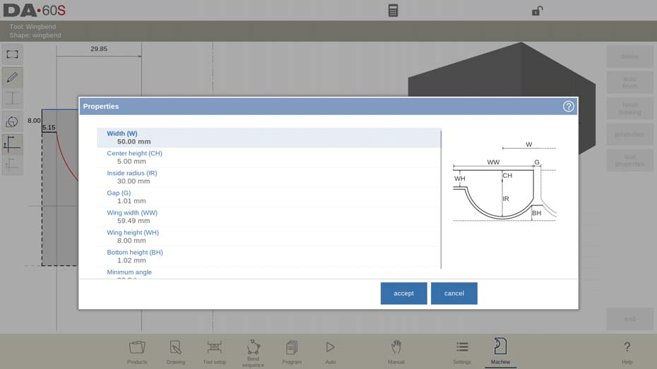
After defining these parameters, you can create a tool drawing using the drawing facilities within the DELEM DA-69S Machine Mode. Enter angle values and line lengths, or use the Touch drawing tools for precision.
DXF import (only available when DXF option has been installed)
If the DXF option is installed, you can import wingbend die shapes. Ensure the die’s body is in layer 0 and the wing in a different layer within the DXF drawing for accurate import. Closed contours for both parts are necessary for successful uploads.
Tool Setup and Customization
To configure the machine geometries in the DELEM DA-69S Machine Mode, follow these steps for optimal setup and collision detection:
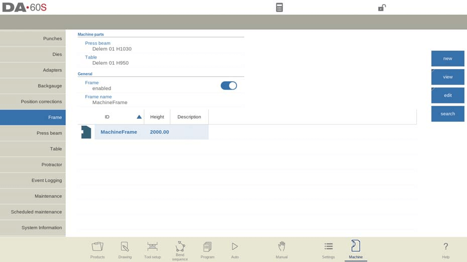
- Select Active Geometries: Within the DELEM DA-69S Machine Mode, choose the active geometries, which include the press beam, table, and side frames. These choices are crucial for accurate machine operation.
- Set Machine Identification: Program the machine identification on this tab to ensure that all configurations are properly logged and identifiable during operations.
- Program Frame Dimensions: Define the frame dimensions directly within this page. This step is essential for precise machine alignment and functionality.
- Graphical Programming and Collision Detection: Utilize the simulation screen to view the machine shape during graphical programming. This visual aid is key to detecting potential collisions between the workpiece and the machine, ensuring safe and efficient operations.
At the top of the screen the possible machine parts can be selected. The selected machine parts are used when a new tool configuration is programmed.
- Press Beam
- Select the appropriate press beam from the top menu.
- Table
- Choose the relevant machine table for your setup.
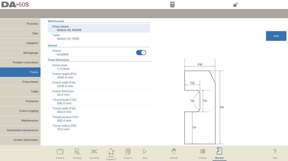
- Frame Settings
- Enable/Disable: Determine if frame design is needed based on side frame position.
- Type: Choose between C-frame and O-frame.
- Dimensions: Set height, width, and thickness.
- Throat Configuration
- Dimensions: Set the height and width of the throat.
- Position and Radius: Specify throat position and corner radius.
Utilizing the C-frame contour editor
- Open Contour Editor: Launch the contour editor in DELEM DA-69S machine mode.
- Draw Basic Shape: Start with the basic C-frame outline.
- Add Radii: Insert radii between or within lines for smoother transitions.
- Detail the Design: Refine and complete the contour with precise detailing.
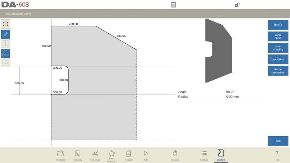
These steps help optimize the creation of a C-frame contour in the DELEM DA-69S machine mode.
Adapters
On this page the tool adapters can be enabled and programmed.
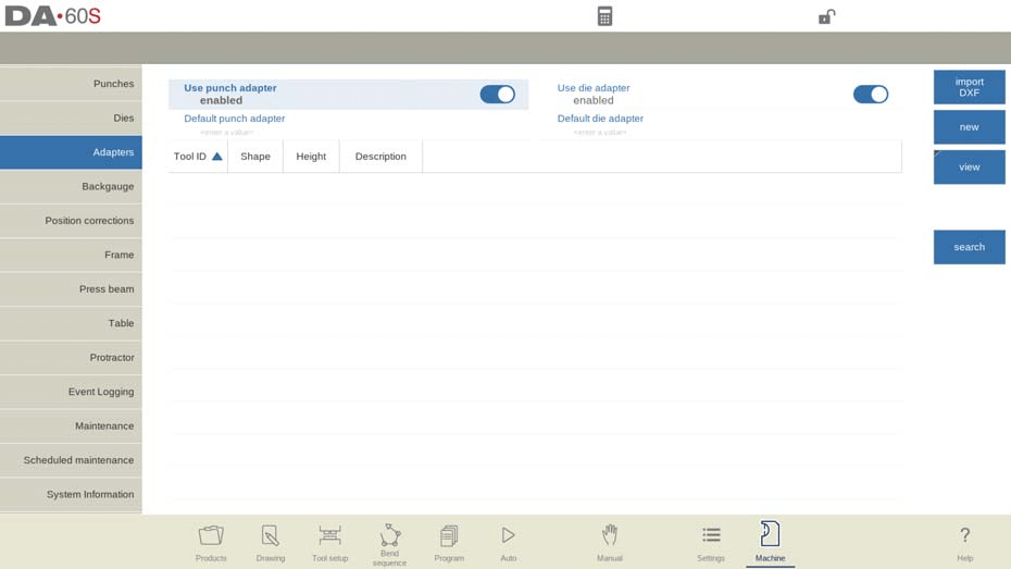
Optimize and streamline your tool adapter setup with these easy steps:
- Enable Adapters: Activate upper or lower adapters as required.
- Set Default Adapter: Select a default adapter for automatic loading with tools.
- Add New Adapter:
- Shape: Choose between punch (press beam) or die (table).
- ID & Description: Assign unique identifiers (max 25 characters).
- Support Type: Choose ‘head’ or ‘shoulder’ mounted.
- Resistance Settings: Define allowable force; ‘0’ to skip checks.
- DXF Import: Load adapter shape through this function (if enabled).
- Program Mount Points: Optionally set connection points in the drawing.
- Default Adapters for Tools: Mark commonly used combinations as default for easy access.
Backgauge
With the backgauge finger dimensions the R-axis movement and related X-axes movement is taken into account. Also the workpiece / backgauge collision is computed using the dimensions.

Default lay on position
The default lay-on position is automatically used during bend sequence computation if the X-axis position exceeds its allowed range or the ‘Lay-on backstop limit’. This default setting ensures continuity and accuracy in operations when manual lay-on level selection isn’t applied. Meaning of lay-on numbers:
Lay-on = 0

Lay-on = 1
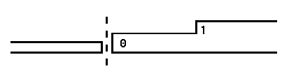
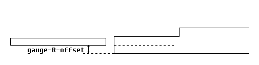
Gauge R offset
An offset value for the R-axis can be set if the backgauge is positioned against the sheet edge and the X-axis position is outside the die safety zone. A negative value gives a lower backgauge position. This offset is only valid for gauge position 0.
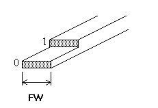
Finger width
The width of the backgauge finger. Only available when automatic Z-axes have been installed.
Finger radius
The radius of the tip of the backgauge finger. A value of 0 means no radius. Only available when automatic Z-axes have been installed.
Tap Edit backgauge to make the backgauge drawing appear wherein the dimensions of the backgauge finger can be programmed.
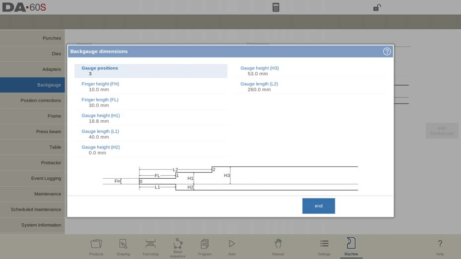
- Set Gauge Positions (Max. 4):
- Adjust the number of gauge positions; this updates the finger geometry and available parameters.
- Program Finger Dimensions:
- Finger Height (FH): Thickness of the first finger tip.
- Finger Length (FL): Length of the first lay-on level.
- Configure Gauge Heights:
- Heights (H1, H2, H3, H4): Set heights for lay-on levels and bottom gauge.
- Set Gauge Lengths:
- Lengths (L1, L2, L3): Define lengths for finger and lay-on levels.
- Visual Adjustments:
- Illustration updates with changes, aiding precision.
Use this guide in DELEM DA-69S Machine Mode for efficient backgauge setup.
Backgauge finger library
When more than one set of backgauge fingers are programmed, they are shown in a library of fingers. When special fingers are installed, the database is activated enabling more finger sets.
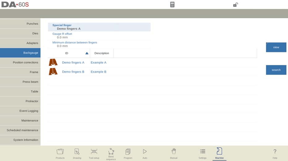
- Finger Selection: Match selected fingers with those used for CNC program generation.
- Manage Special Fingers: Modify name/ID and choose from the library.
- Minimum Distance: Set absolute minimum spacing; 0 disables the setting.
- Edit Special Fingers: Adjust X Offset for length difference from reference finger.
- Deleting Finger Sets: Reactivates parameterized finger definition.
Position corrections
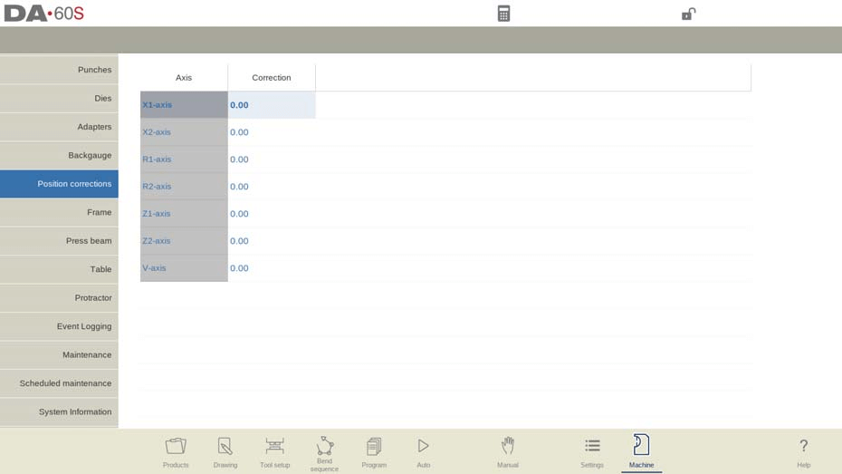
- Check Discrepancy:
- Compare displayed and mechanical axis positions.
- Calculate Difference:
- If displayed is 250 and actual is 252, correction is -2.
- Set Correction:
- Input the difference to correct position.
- Auxiliary Axes:
- Apply corrections to all needed axes.
- Temporary Use:
- Reset corrections to 0 after servicing for normal use.
Use this guide for precise position corrections in DELEM DA-69S Machine Mode.
Advanced Operation Features
Press beam
Program the press beam’s geometry on this tab for collision detection. Special utilities can be added as custom shapes for accurate collision calculations. Typically, only one shape is programmed.
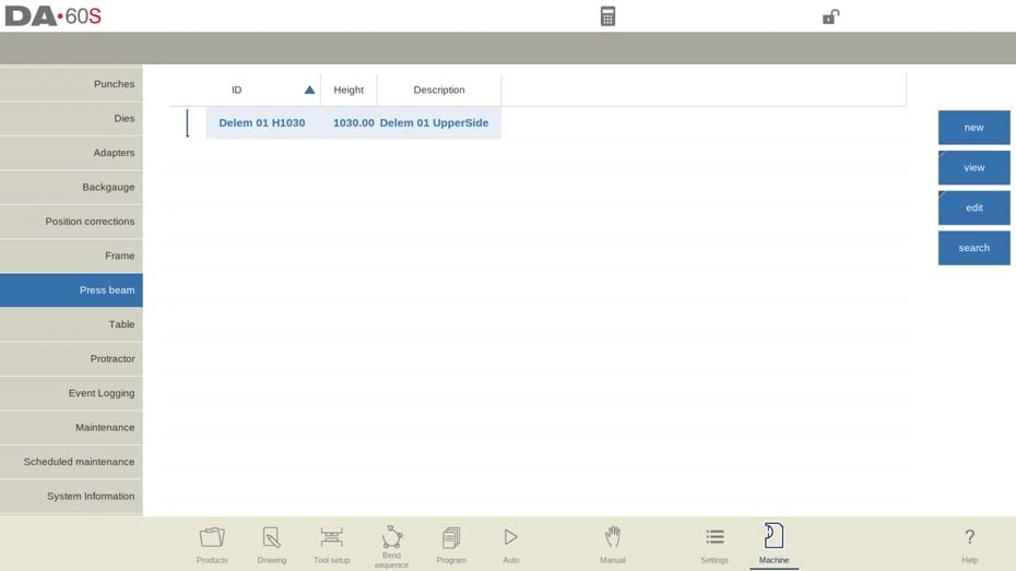
In DELEM DA-69S Machine Mode, the machine shapes are drawn similarly to punches and dies, with the right side of the drawing indicating the backgauge position. For a detailed view, go to the library tab, select “View”, and choose “Graphical”.
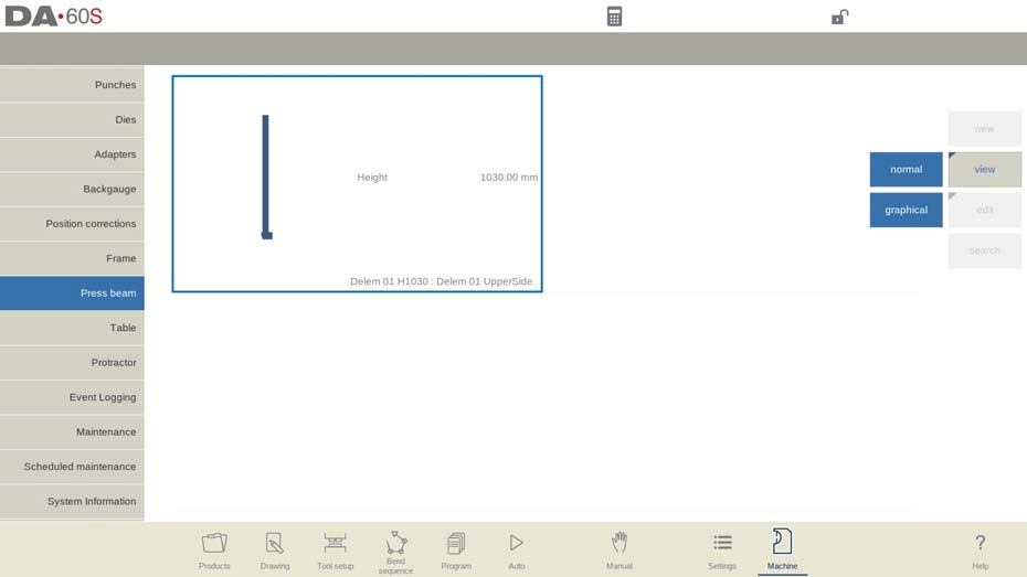
In the DELEM DA-69S Machine Mode, creating a new machine part involves several key steps:
- Library Access: Tap “Edit” and select “Add”.
- Enter Details:
- ID: Unique identifier, max 25 characters.
- Description: Name, max 25 characters.
- Height: Total height of the part.
- Tool Holder Resistance: Set maximum force; 0 disables checks.
- Press Beam Height: Define when the upper part is at its top position.
- Drawing Editor: Sketch parts or input dimensions. Optional DXF import if available.
- Mount Point: Identify connection point for punch/adapter, if enabled.
Table
In this tab the machine geometry for the table, as a profile, can be programmed.

- Start Editing
- Go to the geometry tab and tap “Edit” to add a new machine part.
- Input Parameters
- Enter a unique ID and description (max 25 characters each).
- Specify the part’s height.
- Tool Holder Resistance
- Set the maximum force allowed, or input 0 for no check.
- Draw the Part
- Use the editor to sketch or input measurements.
- Import shapes via DXF if available.
- Set Mount Point (Optional)
- Indicate connection points and configure the I-axis. Default is 0 (centered).
- Adjust I-Axis Division
- Modify the division line to separate stationary from dynamic parts.
Drawing functionality for tools, adapters and machine shapes
When programming shapes such as punches, dies, and machine adapters using the DELEM DA-69S Machine Mode, you have the flexibility to create precise and realistic designs. Here’s a concise guide on how to effectively use this functionality:
- Access the Drawing Functionality:
- Use the DELEM DA-69S Machine Mode to enter the shape programming section after you’ve input the main data.
- Sketch the Desired Shape:
- Initially sketch the desired shape. This provides a visual framework that can be incrementally refined.
- Modify Segments for Precision:
- Change individual segments of the sketch to program their precise dimensions. This step ensures accuracy in the final shape and aids in collision prevention.
- Incremental Design Approach:
- Alternatively, begin by programming the first drawn segment and proceed step by step, refining each subsequent segment.
By following these steps in DELEM DA-69S Machine Mode, you can leverage its drawing functionality to create accurate and collision-free machine components.
Important to know is the following:
- Closed Shapes Required: Ensure shapes are closed; use the auto-finish function if needed.
- Object Height Matters: The programmed object’s height is crucial for accurate bending calculations.
Helpful to know can be the following:
• A line as well as an angle can be given a radius.
• Snapping will help to align lines and angles to its surroundings.
• A line’s length, projection dimensions, and angle are key for programming it accurately. The control system aids by accommodating your last input, adjusting values as needed. This flexibility is crucial since drawings can vary in detail dimensions.
• Help lines in DELEM DA-69S allow you to measure inter-point distances and adjust points based on desired measurements. When you select a point, help lines appear; by moving these lines to reference your target value and changing the dimension, the point will automatically adjust to the specified location.
• For your convenience the help lines can be switched off, giving a non disturbed view to what you have drawn.
• In case the control is using mount points in the tool details, the mount points can be toggled with the drawing. This will prevent from accidental non desired changes to either mount point position or shape details.
DXF import for tools, adapters and machine parts (only available when DXF option has been installed)
In DELEM DA-69S Machine Mode, the tool library for punches, dies, adapters, and machine shapes includes a DXF import function. This feature allows you to import contours from a DXF file.
By selecting “Import DXF”, you open the file browser to choose your desired DXF file. Depending on the screen, the system displays the file and lets you adjust conversion settings, such as layer selection, to import the required contour information.
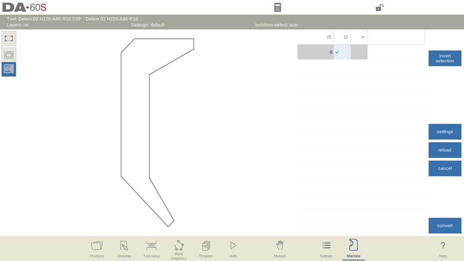
When Convert is chosen, automatic shape detection or specific shape selection can be selected as well as the name ID of the new tool can be given. The tool is then converted and opens in edit mode in the tool editor, where attributes like Tool height, Mount points, and properties can be set. After saving, the tool is added to the library for further use or editing.
For machine DXF imports, this applies to tools like Punches, Dies, and more, ensuring the tool body is in layer 0 and specific parts in designated layers for automatic type detection.
Conversion of special tools
Converting special tools requires that the tool body is in layer 0 of the DXF drawing. For components like the top part of an inside hem die, wing of a wingbend, or the movable part of the vario V, place them in separate layers named ‘Inside hem’, ‘Wing’, or ‘Vario V’. This enables automatic tool type selection by the importer, though manual selection is also possible. Ensure both parts in the DXF are closed contours.
Frequently Asked Questions(FAQ)
How can I optimize the DELEM DA-69S Machine Mode for my press brake operations?
To optimize the DELEM DA-69S Machine Mode, ensure your press brake is properly calibrated and all software updates are installed. Familiarize yourself with the machine’s interface and utilize its help lines feature for precise adjustments.
What should I do if the special tools are not correctly recognized in the DELEM DA-69S Machine Mode?
Make sure that the body of the tool is set in layer 0 within your DXF drawing. For components like the inside hem die or wingbend, assign them to specific layers named ‘Inside hem’ or ‘Wing’. This helps the system automatically detect and assign the correct tool type.
Conclusion
Mastering the operation of the DELEM DA-69S Machine Mode is crucial for optimizing the productivity and precision of your press brake processes. Key steps include familiarizing yourself with the control interface, accurately setting up DXF files with appropriate layers, and utilizing the help lines function for precise adjustments. By adhering to these guidelines, you can enhance operational efficiency and ensure superior machining outcomes.
For further assistance or to gain more in-depth technical insights, feel free to reach out to our team. Additionally, explore our documentation library for related articles and resources to expand your knowledge of machine settings and capabilities.


