


When setting up the DELEM DA-53T Manual Mode, it’s crucial to understand the steps involved in configuring your press brake for optimal performance. I’ll guide you through the process of setting DELEM DA-53T to Manual Mode, ensuring you know how to fine-tune your machine effectively.
With this mode, you have full control over the bending process, enabling precise adjustments and maximized output quality. Whether you’re new to using DELEM controllers or seeking to enhance your setup, this article will provide you with the detailed steps you need to get started and fully utilize your press brake’s capabilities.
Step 1: Accessing Manual Mode
Begin by turning on the DELEM DA-53T controller. Upon startup, navigate to the main menu using the interface keys.

Locate and select the ‘Manual Mode’ option from the list. This will switch the controller interface from automatic to manual settings.
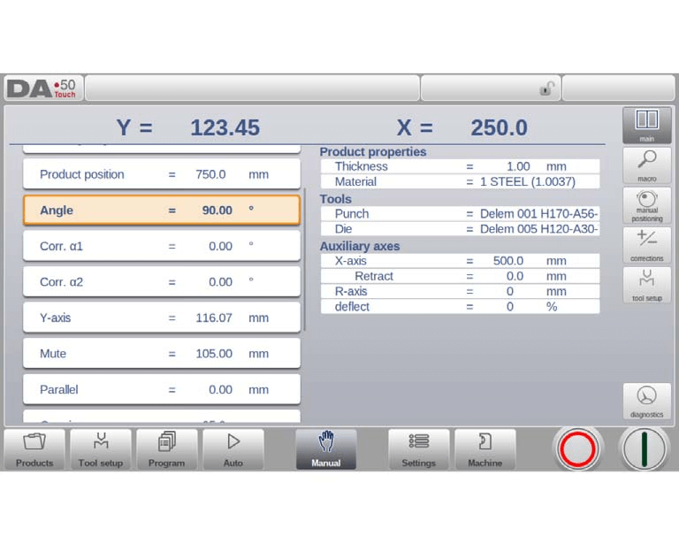
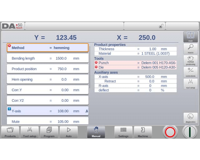
In the top of the Manual mode screen you can find the Y-axis and the main X-axis current position. All other axes and functions are listed one by one in the two columns below.
When these Y-axis value and X-axis value are highlighted it means that the reference markers of these axes have been found and that they are positioned correctly referred to their programmed values.
Step 2: Understanding Parameters
Once in manual mode, input the required parameters for your operation. This includes setting up the press brake’s stroke, speed, and positioning, which are critical for accurate manual operation. This mode is useful for testing, for calibration and for single bends.
Use the data entry buttons to input the numerical values corresponding to your desired settings.
Following is a list of the available parameters in Manual mode.
Bend Parameters
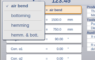
Method:
Select the desired bending method. DELEM DA-53T Manual Mode supports various methods such as Air Bend, Bottoming, Hemming, and Hemming & Bottoming. These methods are elaborated in Program Mode documentation.
Bending Length:
Input the sheet’s bending length for accurate processing.
Product Position:
Set and monitor the absolute position in the Z-direction with a reference value of zero on the machine’s left side.
Angle:
Define the bending angle. Correct any angle discrepancies by adjusting corrections α1 and α2. For example, if a programmed angle is 90 degrees and the measured angle is 92 degrees, adjust Corr.α to -2.
Hem Opening:
Determine the opening distance between flanges during a hem bend, with default settings available in Settings Mode.

Corr.Y:
Correction on the Y-axis position, in case bottoming has been selected.
Y-axis:
The programmed or calculated Y-axis value to realise a certain angle.
Mute:
Sequence point where the Y-axis is switched from fast closing speed to pressing speed. It is programmed here as a Y-axis position value. The programmed value is the Y-axis point above the sheet.

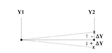
Parallel:
Difference of the left- and right hand side cylinder (Y1 and Y2). When positive, the right hand side is lower. When negative, the right hand side is higher. The programmed value is active below the clamping point.
Opening
This parameter results in a certain gap opening between the punch and the die after the bend. A positive value is the gap opening above Mute, a negative value below Mute. When you want to limit the handling time for the product you can program a small positive or a negative value.
Force Parameters
Force:
Program the pressing force for operations, ensuring optimal pressure application.
Dwell Time and Decompression:
Set the hold time at bending point and decompression distance to manage pressure release.
Speed Parameters
Speed:
Pressing speed, the speed of the Y-axis during bending.
Decomp speed:
The decompression speed is the programmable speed of the beam during the decompression distance.
Functions
Wait for Retract:
Decide whether the Y-axis waits for retract completion or moves as retract begins, ensuring efficient workflow.
Product Properties
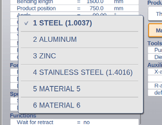
Thickness and Material:
Enter sheet thickness and select materials from 99 custom material entries on the control for bending depth calculation.
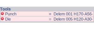
Tools
Punch and Die:
Select or modify punch and die IDs from the respective libraries for the task.
Auxiliary Axes
Auxiliary axis:
If you have one or more auxiliary axes (for instance an X-axis, R-axis or Z-axis) the parameters of these axes appear here.
Retract:
The retract distance of the axis during the bend. The “backgauge retract” is started at the pinching point.
Speed:
Speed of the axis in the current bend. Speed can be programmed in a percentage of the maximum possible speed.
By programming these parameters efficiently in DELEM DA-53T Manual Mode, you ensure accurate and precise bending operations. Once all settings are confirmed, pressing the Start button activates these configurations.
Tool setup
The tool setup programming for the DELEM DA-53T Manual Mode closely resembles that of Automatic Mode. While each mode allows for a unique tool setup, the setup from Automatic Mode can be applied in Manual Mode. When switching to Manual Mode, the DELEM DA-53T controller offers the option to use the existing tool setup. However, users should exercise caution if the setup differs from previous programming.
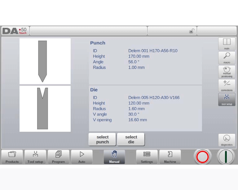
Adding tools ( Punches / Dies )
Same as in Tool Setup, via the Add function tools can be added.
Step 3: Configuring Parameters
Parameters in manual mode for the DELEM DA-53T Manual Mode can be individually programmed. The system automatically computes the effect of each parameter on others. Relationships between parameters are visually represented with symbols and background colors.
When a parameter has been altered, an information symbol appears.

A star symbol indicates that a parameter’s value differs from the calculated control value, which can be helpful when values are intentionally set differently or are limited.

An error symbol appears when a parameter value is incorrect, such as if a hemming bend is programmed without hemming tools.
View Options
Command buttons on the screen’s right side provide access to additional views beyond the Main view, including Macro, Manual Positioning, Corrections, and Diagnostics views.

Macro
With Macro, the DELEM DA-53T Manual Mode switches to a new view featuring large axes values on the screen. This layout is useful for reading axis values clearly when working slightly away from the control.
Step 4: Making Manual movement of the axes
Movement Procedure
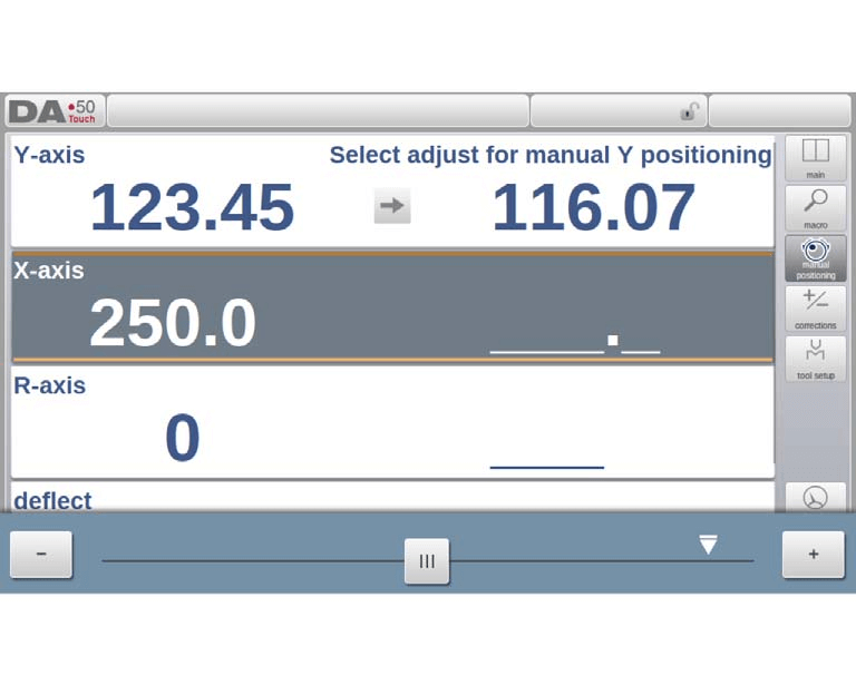
For manual movement of an axis in DELEM DA-53T Manual Mode, use the slider at the bottom of the screen. After selecting “Manual Pos” on the main screen, a new interface will display. Move any shown axis by adjusting the slider from its central position, which returns automatically when released.
Auxiliary Axes
Ensure the control is stopped (Stop button on). Select the desired back gauge axis, and position the cursor there. Move the axis using the slider.
Y-Axis
Manual positioning of the pressbeam, similar to auxiliary axes, requires these conditions:
- The control must be active (Start button on).
- Activate the ‘adjust’ function; if inactive, a message will appear in the upper right corner.
- The Y-axis must be below mute-point.
- A CNC pressing command must be issued.
Teach
To store a position after manually moving an axis, tap the axis name in the Programmed column. This action copies the actual value (left side) to the programmed field (right side).

Upon returning to the default manual mode screen, the axis parameter retains the recently stored value.
By following these steps, you ensure a smooth operation in DELEM DA-53T Manual Mode.
Corrections
In the DELEM DA-53T Manual Mode, corrections for bends programmed in this mode are displayed.
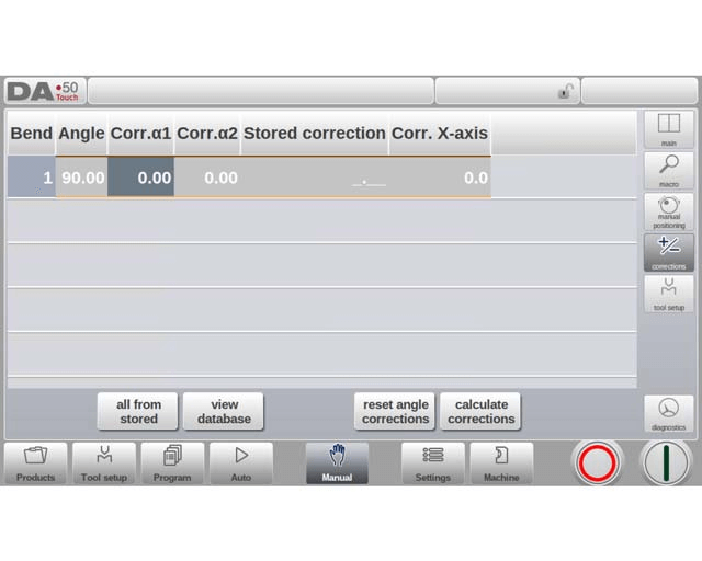
As this involves a single bend, you’ll see a single line of information. The programmed corrections in Manual Mode can be verified just like those in automatic mode. Entries in the correction database and initial corrections are also visible here. Accessing the database is crucial, as these entries significantly influence the bend results. This feature is particularly useful for adjusting corrections during test bending and storing the optimal results in the database.

Diagnostics
When navigating the DELEM DA-53T Manual Mode, tapping Diagnostics provides a view of axes states. This window displays the current status of available axes and can remain active when the control is initiated. Utilizing this feature allows for real-time monitoring of control behavior during a bend cycle, enhancing operational precision.

IO status
In DELEM DA-53T Manual Mode, tapping on the I/O tab within Diagnostics provides a comprehensive view of the current state of inputs and outputs. This screen remains active when the control is started, allowing operators to monitor system behavior throughout the bend cycle effectively.

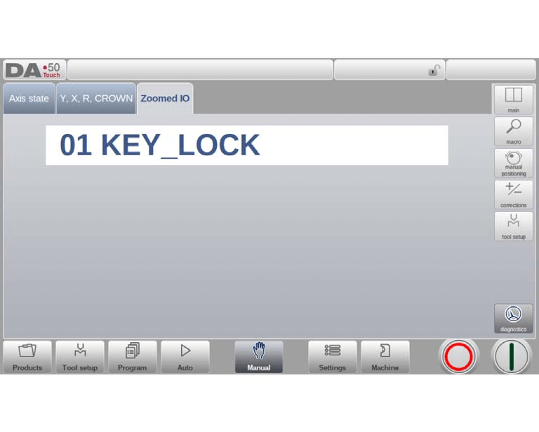
Zoomed IO
When tapping on one or more (up to 5) pins an extra page Zoomed IO is created with an enlarged view of the selected IO; selected pins will be shown in large, enabling distant monitoring.
Frequently Asked Questions(FAQ)
What precautions should I take when operating the DELEM DA-53T in manual mode?
Always ensure all safety protocols are followed. Double-check that the work area is clear of any obstructions and that protective equipment is worn. Familiarize yourself with the manual controls to prevent any mishaps during operation.
What is the recommended frequency for maintaining the DELEM DA-53T while in manual mode?
Routine maintenance should be performed every 500 hours of machine operation. This includes inspecting key components, cleaning the machine, and lubricating the moving parts to ensure smooth operation and longevity of the machine.
Can the DELEM DA-53T manual mode be used for all types of bending operations?
While the manual mode of DELEM DA-53T is versatile, it is primarily designed for operations that require manual adjustments and oversight. For more complex or automated tasks, consider using the CNC capabilities of the DA-53T.
Conclusion
In setting the DELEM DA-53T to manual mode, it’s crucial to follow the outlined steps to ensure proper operation and optimal performance. The process involves initializing the controller, selecting the manual operation mode, and configuring the necessary parameters to suit your specific press brake requirements. This concise approach will help enhance operational efficiency and reduce errors.
Proper setup and maintenance are essential to ensure the longevity and performance of your press brake machine. By following these guidelines and performing regular maintenance, you can minimize downtime and improve production efficiency. For more detailed support or questions, don’t hesitate to contact our team. Additionally, we encourage you to explore other documentation available on our website for further insights and technical support.


