


When it comes to CNC press brake operation, ESA S875 Dies Setup is one of the most critical steps for achieving accurate bends and safe, collision-free production. If you are wondering what the correct steps for ESA S875 dies setup are and how to properly select, enter, and configure dies in the controller, this guide is designed to give you a clear answer. In this article, I explain the complete ESA S875 dies setup process in a practical, step-by-step way, helping you understand how die selection, drawing, and data management affect bending accuracy and machine performance. Whether you are new to the ESA S875 controller or looking to optimize your current setup, this overview will help you set up dies correctly and improve overall press brake efficiency.
How to Access the Dies List on ESA S875 Controller
Step 1: Displaying the Dies List in ESA S875
To begin the ESA S875 dies setup, you must first access the tools list on the controller interface.

Press to display either the punches list or the dies list.
If the punches list appears, press the same key again to switch to the dies list.
Once the dies list is displayed, the screen is divided into three functional areas:

- Left window: Displays the list of available dies
- Center window: Shows detailed data for the selected die
- Right window: Provides a visual preview of the selected die
This layout allows operators to quickly identify the correct die, especially when managing a large number of tools.
Step 2: Using Preview and Selection Functions
For faster identification during ESA S875 dies setup, the preview function can be enabled to display a graphical representation of the selected die.
If preview is not required, it can be disabled through the system menu by selecting the [Preview] option and toggling it off. Repeating the same operation will re-enable it.
To improve navigation efficiency:
- Use [List] to move the cursor back to the dies list
- Use [Selection] to manually enter the die name and quickly locate a specific tool
Scrolling can also be performed directly on the touch panel, which is especially useful when many dies are available.
Managing Dies Data in ESA S875
Step 3: Copying, Renaming, and Deleting Dies
Efficient die management is an important part of long-term ESA S875 controller usage.
The system allows users to:
- Copy a die to create a new tool based on existing dimensions, ideal for similar bending applications
- Rename a die to maintain clear and standardized tool naming
- Delete unused dies to keep the database clean and reduce selection errors
These functions help maintain an organized tool library, which is especially important in high-mix or multi-shift production environments.
How to Enter a New Die in ESA S875
Step 4: Choosing Between Drawn Dies and Preset Dies
When entering a new die, ESA S875 provides two setup methods:
- Preset dies with fixed, adjustable parameters
- Fully drawn dies created from scratch
Preset dies are recommended when the actual tooling closely matches one of the predefined die types, as this significantly reduces setup time. Fully drawn dies are required when:
- The die does not match preset categories
- Multiple cavities are used
- Special shapes, square cavities, or pressing cavities are involved
Accurate die entry is critical because the die drawing is used for collision detection, while bending depth calculations rely on the dimensional data.ng depth calculations rely on the dimensional data entered.
Step 5: Creating a Fully Drawn Die
For non-standard tooling, ESA S875 allows full die drawing through the [New Drawing] function.
After entering the die height and width, the system opens the drawing mask. The drawing interface includes:

- A main drawing window on the left
- Data input windows for polar, Cartesian, V-cavity, and square cavity parameters on the right
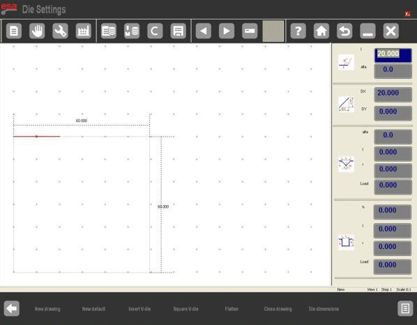
The die must be drawn in a clockwise direction, keeping in mind that the stop position is located on the right-hand side. This ensures correct interpretation by the CNC system.
Step 6: Modifying and Saving Preset Dies
Preset dies are displayed as pre-drawn shapes with adjustable parameters. When scrolling through data fields, the corresponding dimension is highlighted directly on the drawing, making adjustments intuitive and precise.

After modifying the required values and confirming with [ENTER], the system automatically updates the drawing.
Once the setup is complete, save the die by entering a unique name and confirming with [OK]. This allows the die to be reused in future bending programs.
Best Practices for ESA S875 Dies Setup
Proper dies setup on the ESA S875 controller improves bending accuracy, reduces tool collision risks, and enhances production consistency. For optimal results, always ensure that:
- Die dimensions match the actual tooling
- Drawn dies follow correct orientation rules
- Unused or outdated dies are removed from the system
Consistent and accurate die management allows press brake systems to operate safely and efficiently across a wide range of bending applications.
Frequently Asked Questions(FAQ)
When should I use preset dies instead of fully drawn dies in ESA S875?
Preset dies should be used when the actual tooling closely matches one of the predefined die types in the ESA S875 system. They are faster to set up and easier to modify. Fully drawn dies are recommended when the die has multiple cavities, special shapes, or does not fit into preset categories.
Can I copy an existing die during ESA S875 dies setup?
Yes. The ESA S875 controller allows users to copy an existing die and save it under a new name. This function is useful when creating similar dies with minor dimensional changes, helping reduce setup time and maintain consistency in tooling data.
What are common mistakes to avoid during ESA S875 dies setup?
Common mistakes include entering incorrect die dimensions, drawing dies in the wrong orientation, and using outdated or incorrect die data. To avoid these issues, always verify die measurements, follow the correct drawing direction, and regularly maintain the dies database in the ESA S875 controller.
Conclusion
Proper ESA S875 dies setup is essential for ensuring accurate bending results, reliable collision detection, and stable press brake performance. By following the correct steps—accessing the dies list, selecting and previewing tools, managing die data, entering new dies, and choosing between fully drawn or preset dies—operators can configure the ESA S875 controller efficiently and reduce setup errors. Accurate die dimensions and correct drawing conventions directly contribute to improved bending precision and safer machine operation.
To achieve the best results, it is recommended to keep the die library well organized, verify die parameters before production, and use preset dies whenever possible to save setup time.
For more technical guidance on ESA S875 controllers, press brake tooling, or customized bending solutions, contact HARSLE for professional support, or explore our related technical documentation and product resources on the website.


