


The DELEM DA-66S Manual Mode provides users with the flexibility to perform precise bending operations independently from automatic settings. With Manual Mode, operators can gain full control over the bending process, customizing parameters for each job. This mode is ideal for applications requiring specific adjustments that automated settings may not accommodate.
In this article, we’ll delve into the core functionalities of the DELEM DA-66S Manual Mode, providing you with a comprehensive guide to enhance your machine’s performance and output.
Manual Mode Overview
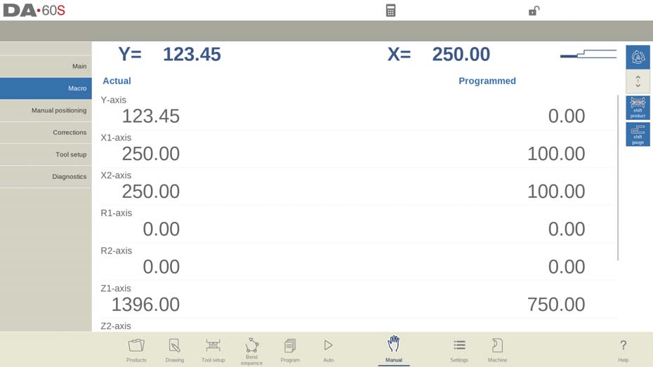
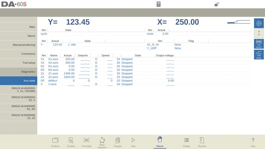
The DELEM DA-66S Manual Mode grants users the ability to manually control the press brake, independent of pre-defined programs. By navigating to Manual Mode, you can view the real-time positions of key axes such as the Y-axis and the main X-axis on the screen. These indicators ensure the reference markers are correctly aligned with the programmed values for precise bending operations.
In manual mode you program the parameters for one bending. This mode is useful for testing, for calibration and for single bends.
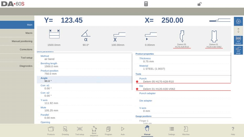
Manual mode is independent from Automatic mode and can be programmed independently of the programs in memory.
In the top of the Manual mode screen you can find the Y-axis and the main X-axis current position. All other axes and functions are listed one by one in the two columns below. When these Y-axis value and X-axis value are highlighted it means that the reference markers of these axes have been found and that they are positioned correctly referred to their programmed values.
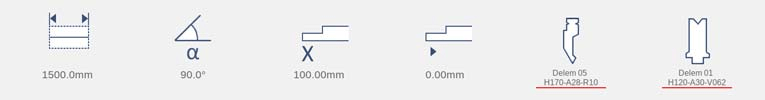
Above the axes and functions, large icons (tiles) with related values are showing the most used ones. These tiles can be selected and the values can directly be modified.
Following is a list of the available parameters in Manual mode.
Bend parameters
Method
Select the required bending method. The control supports the following standard methods:
• Air bend
• Bottoming
• Hemming
• Hemming & bottoming

The bend methods have been explained in more detail in the Program mode.
Deflect method
Dynamic: The crowning will be controlled automatically in real-time during the bending, applying the proper corrections when needed.
Non-dynamic: The crowning will behave as a standard hydraulic crowning; there won’t be real-time corrections.
Bending length
Program the bending length of the sheet.
Product position
The absolute position value of the product in the Z-direction. Left machine side is reference position zero.
Angle
Angle to bend.
Corr.α 1, Corr.α 2
Correction on angle to bend.
The angle correction should be entered as following examples indicate:
Programmed value of 90 degrees. Measured value of 92 degrees. Then it is required to program Corr.α with -2.
Programmed value of 90 degrees. Measured value of 88 degrees. Then it is required to program Corr.α with +2.
Hem opening
The hem bend can be made with a certain opening distance between the 2 flanges. The hem opening value will be used calculating the beam position in the hemming process.
By default this parameter has the value of the Settings mode parameter Default Hem Opening.

Fast hemming
When fast hemming has been enabled, the Y-axis will move at high speed down as soon as it is below the top of the die, until the hemming load opening has been reached. This will reduce the cycle time, especially in case of hemming with a U-die.
Only available when enabled by the machine manufacturer.
Corr.Y
Correction on the Y-axis position, in case bottoming has been selected.
Y-axis
The programmed or calculated Y-axis value to realize a certain angle.
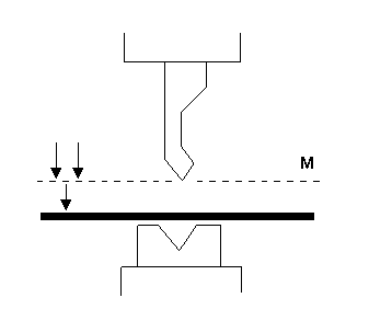
Mute
Sequence point where the Y-axis is switched from fast closing speed to pressing speed. It is programmed here as a Y-axis position value. The programmed value is the Y-axis point above the sheet.
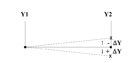
Parallel
Difference of the left- and right hand side cylinder (Y1 and Y2). When positive, the right hand side is lower. When negative, the right hand side is higher. The programmed value is active below the clamping point.
Opening
This parameter results in a certain gap opening between the punch and the die after the bend. A positive value is the gap opening above Mute, a negative value below Mute.
When you want to limit the handling time for the product you can program a small positive or a negative value.
Force
Force
The programmed force applied during pressing.
Dwell time
Hold time of punch at the bending point.
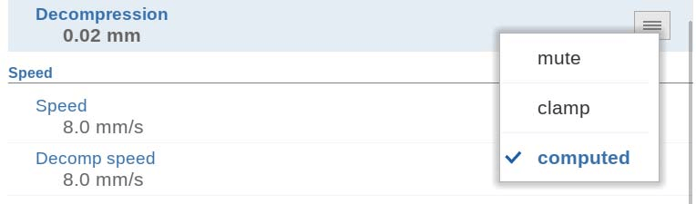
Decompression
Decompression distance after the bending to release the working pressure from the system. The decompression distance can optionally be set to a specific point in the cycle. Standard the decompression distance is computed, the value which is minimal required. Optionally one can chose for Mute, the calculated mute point, or Clamp, the calculated clamping point. Both options have a longer distance than the calculated one.
Speed
Speed
Pressing speed, the speed of the Y-axis during bending.
Decomp speed
The decompression speed is the programmable speed of the beam during the decompression distance.
Functions
Wait for retract
In case of a retract, let the Y-axis wait until the retract is finished, yes or no.
No: the retract is started when the Y-axis passes the clamping point, the Y-axis does not stop.
Yes: when the Y-axis reaches the clamping point, the Y-axis is stopped and the retract is started. When the retract is completed, the Y-axis moves on.
Product properties
Thickness
Program the thickness of the sheet.
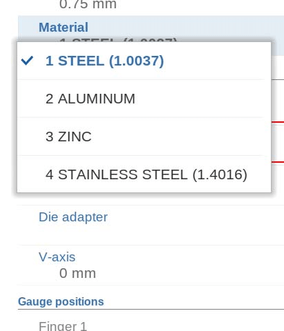
Material
Selection of one of the programmed materials, which are used to calculate the bending depths. The control contains 4 pre-programmed materials. In total, 99 materials can be programmed on the control. The materials can be programmed on the Materials page in the Settings mode.
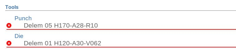
Tools
Punch
The name (ID) of the selected punch. Tap to modify or select from the punch library.
Die
The name (ID) of the selected die. Tap to modify or select from the die library.
Punch adapter
The name (ID) of the selected punch adapter. Tap to modify or select from the punch adapter library. Whether an adapter can be programmed depends on the parameter Use punch adapter in the Machine mode.
Die adapter
The name (ID) of the selected die adapter. Tap to modify or select from the die adapter library. Whether an adapter can be programmed depends on the parameter Use die adapter in the Machine mode.
Gauge positions
Finger (1/2/3/4)
The finger (contact) position, corresponding to the X-axis position and lay on position.
Auxiliary axes
Auxiliary axis
If you have one or more auxiliary axes (for instance an X-axis, R-axis or Z-axis) the parameters of these axes appear here. When you have a R1-axis and a R2- axis the programmed R1-axis value is automatically copied to the R2-axis value. The R2-axis value can, if necessary, be changed afterwards.
Retract
The retract distance of the axis during the bend. The ‘backgauge retract’ is started at the pinching point.
Speed
Speed of the axis in the current bend. Speed can be programmed in a percentage of the maximum possible speed.
Part support
PST-axis
With this parameter the part support can be switched on or off. When it is switched off, the part support will stay at its zero position during the bend.
R-position
The height of the part support before and after the bend. By default, the height will be set at the top of the die (R-position = 0.00 mm). Only available when enabled by the machine manufacturer.
Method
In DELEM DA-66S Manual Mode, you can control how and when the part support returns to its zero position after completing a bend. Options include setting the part support to return when the Y-axis reaches UDP (‘Return at UDP’) or initiating the return as soon as the Y-axis begins opening (‘Return when opening’).
Alternatively, you can use the ‘Product tilt’option to introduce an extra tilt, preventing collision between the product and the punch during Y-axis opening. The ‘Static angle support’ setting allows the part support to hold at a fixed angle, converting it into a stable support table rather than following the product’s movements. Each option offers unique advantages for optimizing machine operations within the DELEM DA-66S Manual Mode.
Tilt angle
The tilt angle determines how much the part support will move. At the machine’s front side, the support moves to a higher position (larger angle), while at the back, it moves to a lower position (smaller angle). This feature is applicable when using the ‘Product tilt’ method.
Tilt speed
This specifies the speed at which the part moves to the tilt angle, expressed as a percentage of the maximum operation speed. It is relevant only when ‘Product tilt’ is selected within the DELEM DA-66S Manual Mode.
Tilt clearance
If the decompression distance is insufficient for tilt movement, an additional ‘Tilt clearance’ can be programmed. This extra distance is included in the programmed decompression distance, ensuring smooth operation. The clearance setting is used exclusively with the ‘Product tilt’ method in the DELEM DA-66S Manual Mode.
Angle
The static angle to which the part support will move before the bend. Only available when method ‘Static angle support” has been selected.
Speed
The speed, as a percentage of the maximum speed, with which the part support moves to the static angle. Only available when method ‘Static angle support’ has been selected.
Return speed
Return speed of the part support after a bend. The speed value is programmed as a percentage of the maximum speed.
Safety stop angle
The angle at which the support will stop during the return movement; the control will switch to stop. An extra start action at the control makes the part support return to its zero position.
Initial angle
The initial angle (typically the pre-bend angle of a two-stage bend) to which the part support will be moved at step change. The part support will follow as soon as the angle of the product passes the initial angle of the part support. Only valid for part support axes in front of the machine.
Initial angle speed
The speed to move the part support to the initial angle. Only valid for part support axes in front of the machine.
Correction
Correction on the part support axes in the DELEM DA-66S Manual Mode is gradually applied during the bending process, starting at the pinching point. By the final bend position, the correction adjusts to match the programmed value. These parameters in the DELEM DA-66S Manual Mode can be easily programmed and modified as needed. Once you press the Start button, the programmed settings become active.
The parameters in DELEM DA-66S Manual Mode can be programmed and adjusted as needed. Once you press the Start button, the configured settings become active.
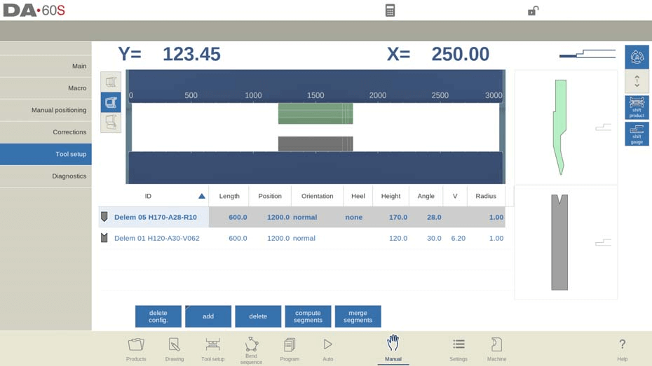
Tool setup
The tool setup in DELEM DA-66S Manual Mode closely parallels its setup in Automatic Mode. Although each mode allows for distinct configurations, you can opt to use the Automatic Mode’s tool setup in Manual Mode, but exercise caution with differing configurations.
In the DELEM DA-66S Manual Mode tool setup menu, you can easily add, remove, or reposition tools such as punches, dies, and adapters. This process mirrors the main Tool Setup functions, enabling custom adjustments to enhance your bending operations. Additionally, segmentation is possible when adding tools, depending on your specific requirements.
Shift product

In the DELEM DA-66S Manual Mode, shifting the product’s position is streamlined using the ‘Shift Product’ function. Snapping points assist users in accurately moving the product, making it easy to align to the side of the tools or the middle of the station.
Key Functions for Product Positioning:
- Jump Left: Shift the product to a different tool set combination on the left.
- Jump Right: Shift the product to a different tool set combination on the right.
- Shift Left: Move the product 1 millimeter to the left within the same tool set.
- Shift Right: Move the product 1 millimeter to the right within the same tool set.
Utilizing these functions in the DELEM DA-66S Manual Mode ensures precise control over product positioning, enhancing both flexibility and accuracy in operations.
Programming parameters & Views
In DELEM DA-66S Manual Mode, you can program parameters individually, with each shown alongside symbols and background colors for easy identification.

An information symbol indicates a change due to a recent input, highlighting adjustments made.

A star symbol alerts you when a parameter value differs from the control’s calculations, useful for deliberate or constraint-limited settings.

Errors are flagged with an error symbol if a value is incompatible with the current program, such as a hemming bend set without appropriate tools.
The right side of the screen provides access to multiple views, including Main, Macro, Manual Positioning, Corrections, and Diagnostics, enhancing user control and monitoring capabilities in the DELEM DA-66S Manual Mode.

Macro
In DELEM DA-66S Manual Mode, the Macro view displays large axis values on the screen, making it easier to read them from a distance. This feature is particularly useful when working remotely from the control panel.
Executing A Safe and Efficient Bending Operation
Manual Axis Movement Procedures
To manually move axes safely, use the DELEM DA-66S’s hand wheel. Ensure the machine is stopped when repositioning auxiliary axes, while the Y-axis requires the system to be active with specific conditions met, such as the ‘adjust’ function being active.
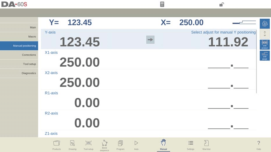
After tapping Manual positioning in the main screen of Manual Mode, the following screen appears:
In the DELEM DA-66S Manual Mode, you can manually move axes using the hand wheel. The steps vary depending on the axis type you’re adjusting.
For auxiliary axes, ensure the machine is stopped (Stop button LED lit). Select the backgauge axis you wish to move, and use the wheel to reposition it.
With the Y-axis, manual positioning is similar but requires that the machine is started (Start button LED on). Additionally, the ‘adjust’ function must be activated (check for messages in the top-right if it’s not). Make sure the Y-axis is below the mute-point and that a pressing command is entered into the CNC.
By following these procedures in DELEM DA-66S Manual Mode, you can safely and effectively manage machine axes.
Teach Mode Utilization
To efficiently teach the DELEM DA-66S Manual Mode control a position discovered by manually adjusting an axis, follow this straightforward procedure. Use the hand wheel to move an axis to your desired position. To save this position, tap the axis name in the Programmed column; the actual axis value from the left will then populate the programmed axis field on the right.

Upon returning to the standard screen of DELEM DA-66S Manual Mode, you’ll find the axis parameter updated with this newly taught value.
Monitoring and Diagnostics for Safe Operations
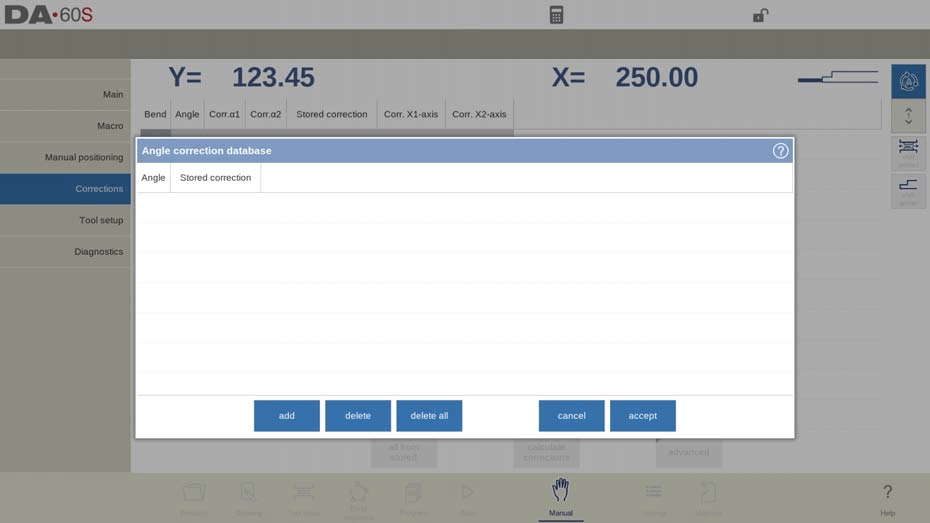
Corrections
In the DELEM DA-66S Manual Mode, you can view and verify corrections for the bends as a single line, similar to how it’s done in Automatic Mode. These corrections and entries in the correction database are crucial for accurate bend results. Access to the database allows you to modify and optimize these corrections, which can also assist in test bending processes.

The Bend Allowance function in DELEM DA-66S Manual Mode enables users to input entries into the bend allowance table. By adding only the necessary bend allowance corrections based on active bend parameters, you can calculate the bend allowance from the difference between programmed and measured values. To activate this feature, switch to the Settings mode.
Diagnostics and Real-Time Monitoring
In DELEM DA-66S Manual Mode, the Diagnostics feature provides a comprehensive view of the machine’s axes states. This functionality allows operators to monitor the real-time status of each axis during a bending cycle. Accessing Diagnostics ensures you can observe how the controls behave, promoting efficient and safe operations.
IO Status Monitoring
The DELEM DA-66S Manual Mode includes a detailed IO status feature, offering insights into the current state of all inputs and outputs. This real-time monitoring is crucial for assessing machine performance and swiftly addressing any potential issues during operations.

Zoomed IO View
For enhanced observation, the Zoomed IO function in DELEM DA-66S Manual Mode allows you to select up to eight pins for an enlarged view. This capability facilitates distant monitoring, ensuring you can track critical inputs and outputs with ease.
Test Bend Mode for Precision
The DELEM DA-66S Manual Mode includes a Test Bend feature designed to fine-tune your bending operations.

Once activated, the axes remain in their retract positions after the initial bend cycle, with the part support maintaining its angle if enabled. This mode halts any step changes.
Upon completing the Test Bend, the Y-axis stops at UDP, allowing operators to measure angles accurately and apply necessary corrections. After adjustments, the bend can be re-executed. The part support resumes following the Y-axis when it returns to its original position. This ensures precise corrections and improved bending accuracy.
Frequently Asked Questions(FAQ)
How do I ensure safety while operating the DELEM DA-66S Manual Mode?
Always follow the manufacturer’s safety guidelines, ensure the machine is properly calibrated, and double-check all axis positions before starting any operation. Proper safety gear and training are essential.
How can I maintain optimal performance of my DELEM DA-66S in Manual Mode?
Regular maintenance is key. Check the machine every 500 hours, inspect essential components, clean the system, and lubricate moving parts according to manufacturer instructions.
How do I apply corrections to the bending angle in the DELEM DA-66S Manual Mode?
Measure the current angle after a bend, then adjust the Corr.α parameters in Manual Mode. This allows you to program necessary corrections and achieve the desired angles accurately.
What should I do if the axes do not return to their original position after a Test Bend?
After the Test Bend, ensure the Y-axis is at the UDP. If the part support does not follow, verify that it is enabled and check for any obstructions or misalignments in the setup.
Conclusion
Operating the DELEM DA-66S Manual Mode safely and efficiently involves understanding its features and regular maintenance. Following the guidelines above and addressing common concerns can enhance machine performance and longevity. For detailed support or more information, contact our team or access further documentation on our website.


