


If you’re seeking a guide on the ESA S640 Punches Setup, you’re in the right place. In this article, I’ll provide a detailed breakdown of the steps involved in setting up punches for the ESA S640, ensuring a smooth and precise operation. This guide is designed to clear your doubts and give you the confidence to perform the ESA S640 Punches Setup efficiently. Whether you are an industry veteran or a newcomer, by the end of this read, you’ll gain valuable knowledge to enhance your metalworking processes with the ESA S640.
Punches List
To begin with the ESA S640 Punches Setup, you’ll need to access the punches list. Follow these procedures to access and manage your tools efficiently:
Accessing the Punch List
Display the List: Press the button to switch between the list of punches and the list of dies. Initially, you may see the dies list, but pressing the button again will display the punches list.
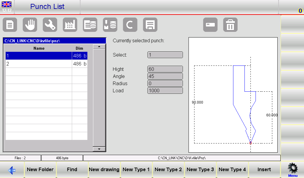
Punch List Window: Once the punches list is displayed, you’ll notice three main sections on the interface:
- The left window shows the entire punch list.
- The central boxes display data related to the selected punch.
- The right window offers a preview of the punch currently selected.
Managing Punches Efficiently
Using Function Buttons: Navigate the punch list using various function buttons:
- [New Folder]: Create a new folder to organize your tools.
- [Find]: Quickly locate a specific punch from the list.
- [New Drawing]: Draw a new punch from scratch.
- [New Type]: Utilize pre-set punch types (Type 1, 2, 3, or 4) to streamline setups.
- [Insert]: Add the selected punch to the work program or specific bend.
Utilizing Previews and Modifications
Display Preview: To identify tools easier, enable the tool preview. This function is typically enabled but can be toggled off if needed. Access the menu and select the 4>> Preview item to manage this setting.
Copying and Renaming:
- Copy a Punch: Select a punch, access the menu, and select 0>> Copy. Enter a new name for the copy and confirm.
- Rename a Punch: Select the punch, access the menu, and choose 1>> Rename. Enter the new name and confirm.
Erasing and Backing Up Tools
Erase a Punch: Select the punch, confirm your selection, and press [Ok] to remove it.
Saving and Deleting Tools to USB:
- Save Tools to USB: Insert a USB device, access the menu, and select 2>> Save Tools to back up all punches and dies.
- Erase All Tools: To clear all entries, select 3>> Delete Tools from the menu and confirm with [Yes].
Handling USB Device Tools
Manage Tools from USB: Insert a USB containing saved tools into the port. Access and manage the list of punches or dies directly from the device, using similar operations to the internal tool list.
Transfer Tools from USB to NC: Save tools from a USB device to the internal NC disk by selecting the 2>> Save Tools option from the menu.
Following these steps for ESA S640 Punches Setup ensures a streamlined workflow and maintains precision across all your metalworking tasks. Proper management of punches and understanding of the interface enhances productivity and reduces setup times.
How to Enter a New Punch for ESA S640
Step 1: Entering a New Punch
To start the ESA S640 Punches Setup, you need to enter a new punch by following these steps:
- Access the Tool Library: Press the

button to display the list of punches.
2. Navigate to Punches Section: If you initially see the list of dies, press this button again to switch to punches.
3. Select and Configure Punch Type: Choose the desired type of punch from the list. You have the option to completely draw a new punch or to use one of the three available pre-set punches with fixed measurements.

These presets can be adjusted to match your requirements.
Note: The punch drawing is essential for performing anti-collision checks with designed workpieces, and the bending depth calculation relies on precise punch dimensions. If fully drawing the punch is challenging, opt for a pre-set type and adjust it to closely fit the actual shape using predefined data.
To proceed, press:
- [New Drawing] to fully design a custom punch.
- [New Type 1] for pre-set punch type 1.
- [New Type 2] for pre-set punch type 2.
- [New Type 3] for pre-set punch type 3.
- [New Type 4] for a round pre-set punch.
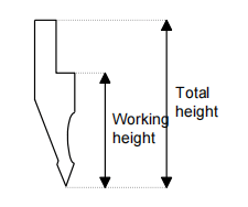
4. Enter Punch Specifications: After selecting the punch type, a new window will prompt you to input dimensions such as total height and working height. Ensure these specifications align with your operational needs.
5. Access the Drawing Page: Once you’ve entered the punch dimensions, access the drawing page by selecting the [Ok] button. The layout of the drawing page will vary depending on the punch type selected. Here, you can finalize the design, ensuring it aligns with the anti-collision checks and bending depth calculations crucial for operational safety and accuracy.
By carefully following these steps in the ESA S640 Punches Setup, you will ensure that your punch setup is precise and efficiently tailored to meet your specific operational requirements.
Step 2: Punches to Draw
After entering punch parameters, the next step in the ESA S640 Punches Setup is drawing the punch using the system’s integrated drawing tool. This ensures an accurate representation of the punch geometry and helps prevent errors.
The punches to draw are accessed through the drawing function, detailed in the relevant chapter of the manual.

The interface comprises a left-hand drawing window and four right-hand windows for data entry, highlighting polar, Cartesian, vertex, and arc drawing data.
Drawing Conventions and Vertex Entry
To ensure accuracy:
- Draw Anticlockwise: Begin drawing the punch in an anticlockwise direction, keeping in mind that the back-gauges are on the punch’s right side.
- Define the Vertex: The tip of the punch is critical for the drawing. Start by entering the length “lp”, then:
- Enter and confirm the tip angle and chamfer, if needed.
- Specify the tip radius (R data item) and press [Ok].
- Input the punch load (maximum tons per meter) and confirm. This sequence draws the tip and proceeds with a default length for subsequent sections.
Detailed Drawing Instructions
Following an example punch, when positioned in Field “lp”:
- Input Tip Data: Enter lengths and angles sequentially.
- Use the Arc Function for Curves: The [Arc] key facilitates smooth, curved sections by entering corresponding length and depth values.
- Adjust Measurements: Use ±1° or ±1mm graphic aids for fine-tuning sections, enhancing the match between the drawing and actual punch.
Correcting and Saving the Drawing
- Corrections: If errors occur, navigate between fields to correct entries.
- Save: Once completed, save the drawing in the system’s memory, naming it with a combination of numbers and letters, and confirm by pressing [Ok].
Step 3: Utilizing Pre-set Punches
The pre-set punch page is presented in the form of a pre-drawn punch along with a series of data that characterize the shape of that punch.
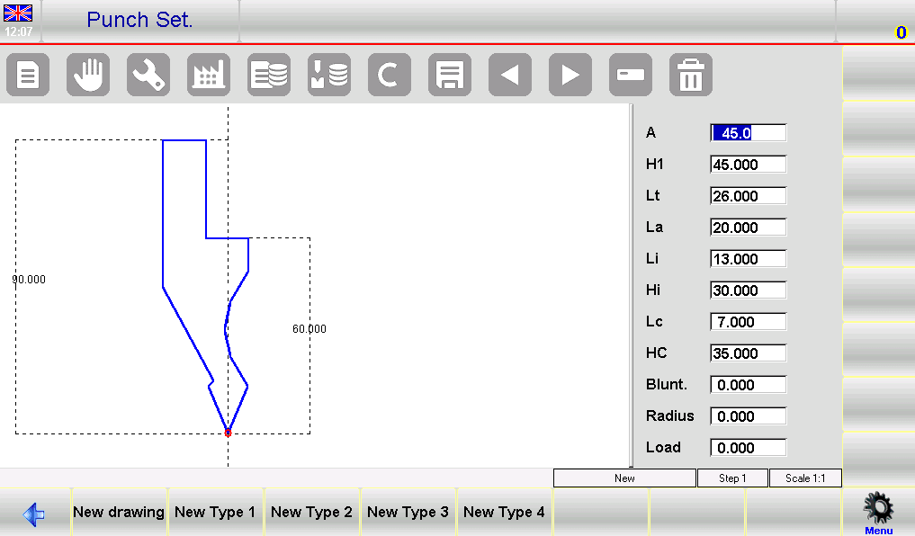
By modifying any one of the values and pressing [Ok], the drawing will be retraced by taking the modified value into account.
How to Save Your Pre-set Punch
After customizing your punch, ensure you save it for repeated use. Press the save button to store the design in the ESA S640’s internal memory. Enter a name comprised of numbers and letters, perhaps using the punch’s catalogue code, and confirm by clicking [Ok]. This process secures your setup, allowing for swift access in future operations.
Finalizing the Setup
After configuring punches, perform a system check to verify all entries and drawings are correct. Doing so minimizes the risk of errors during operation and ensures high precision in all press brake tasks.
By following these detailed steps for setting up punches and dies on the ESA S640, you maximize the system’s capabilities and enhance your production efficiency. Accurate setup is key to achieving precision and prolonging the lifespan of your equipment.
Frequently Asked Questions(FAQ)
What are the recommended intervals for checking and updating my ESA S640 Punches Setup?
It is advisable to review and update your ESA S640 Punches Setup every 300 to 500 hours of operation. Regular checks include verifying tool integrity, recalibrating settings, and cleaning to ensure optimal performance.
Can the ESA S640 system accommodate custom punch designs during setup?
Yes, the ESA S640 system allows for full customization of punch designs during setup. Use the [New Drawing] feature to create and save custom punch configurations tailored to specific project needs.
What steps should I follow if a punch is not aligned correctly in the ESA S640 Punches Setup?
If you encounter misalignment, first review the alignment procedures outlined in your manual. Ensure that the punch is properly seated and configured in the software. Utilize the preview function to confirm that the punch is visually aligned before operation.
Conclusion
In summary, the ESA S640 Punches Setup involves several key steps that ensure optimal performance and precision in your metalworking operations. By accessing and managing the punches list efficiently, utilizing pre-set punch types, and performing regular maintenance, you can greatly enhance the functionality and longevity of your press brake machine.
To take the next step, we recommend contacting HARSLE for more detailed support or any questions you might have about the ESA S640 Punches Setup. Additionally, feel free to explore our other documentation for further insights and guidance on maximizing your equipment’s productivity.


