


Programming punches in the DELEM DA-66T Machine Mode is an essential skill for achieving precise metal shaping and bending. If you’ve been searching for detailed guidance on how to effectively program punches using this advanced CNC controller, you’re in the right place.
Here, I’ll outline the step-by-step process of programming punches, allowing you to harness the full potential of the DELEM DA-66T Machine Mode. Whether you’re new to CNC programming or enhancing your existing skillset, this guide will provide the insights needed to optimize your press brake operations with precision and efficiency.
Introduction

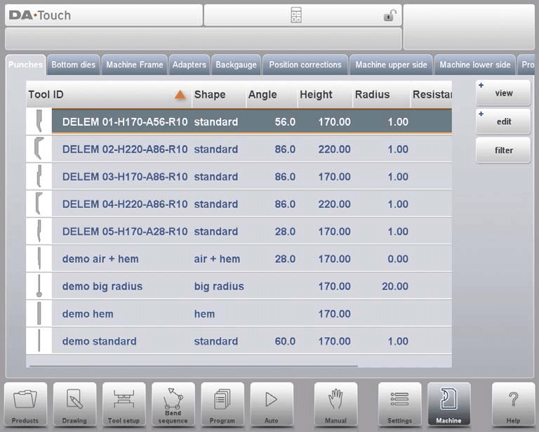
By tapping the navigation button Machine the control is switched to Machine mode.
The DELEM DA-66T Machine Mode, accessible via the navigation panel, is essential for configuring your machine’s settings and specific characteristics that affect its calculations and behavior. The settings are logically organized into several tabs, each covering different aspects of the machine’s functionality.
To navigate through these tabs, simply tap on them to select and adjust the desired settings. If there are more tabs than can be displayed on the screen simultaneously, you can scroll horizontally to view and select additional tabs. This intuitive navigation helps streamline the programming process, especially when working with punches in the DELEM DA-66T Machine Mode.
Programming of Punches in DELEM DA-66T Machine Mode
In this tab, the punches used in the machine, can be programmed. New punches can be added, existing punches can be edited and also deleted.
View
In the DELEM DA-66T Machine Mode, the main page displays a list of available punches. You can utilize the View function to choose different display options, similar to what’s available in Products mode. Aside from the default Expanded view, you can also select Graphical and Graphical Heel views to suit your needs.
Graphical directory
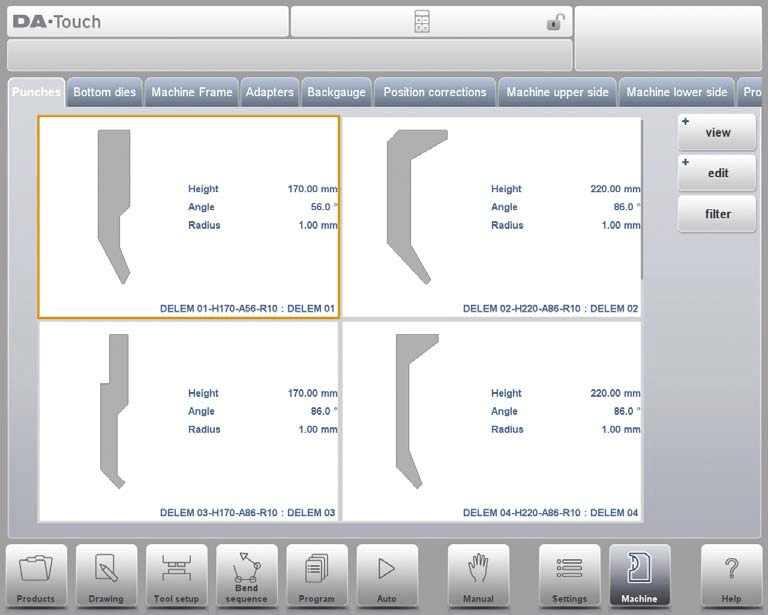
In Graphical the geometry of the tools is shown as well as the main properties.
Graphical directory punches with heels
In Graphical Heel the geometry of the tools is shown as well as the heel properties.
Create a New Punch
Programming a new punch in the DELEM DA-66T Machine Mode involves a few straightforward steps. Here’s a simple guide:
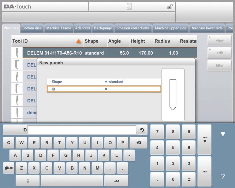
- Access the Library: Tap ‘Edit’ in the library section and select ‘New’ to begin creating a new punch profile.
- Basic Shape and ID:
- Basic Shape: Choose from various punch shapes based on your needs:
- Standard Punch: Ideal for air bending and basic bottoming.
- Hem Bend Punch: Designed for specific hem bends with a flat bottom.
- Air + Hem Bend Punch: Suitable for both air bends and hem functions.
- Big Radius Punch: Used for large radius bends.
- ID: Assign a unique name or number (up to 25 characters, alphanumeric) to identify the punch.
- Basic Shape: Choose from various punch shapes based on your needs:
- Detail the Shape: After selecting the basic shape, follow the wizard to program shape details.
- Finalizing the Punch: Once the basic shape and ID are set, hit ‘Accept’ to proceed to input the tool data parameters.
After accepting, a pop-up will guide you through entering the initial dimensions and properties specific to the chosen shape. This customization ensures that each punch tool is accurately configured for unique bend requirements.
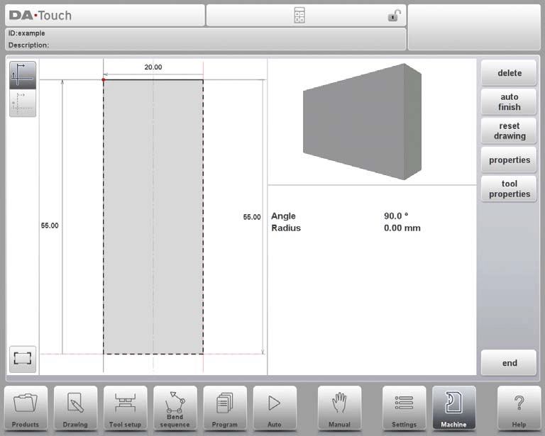
Standard Punch
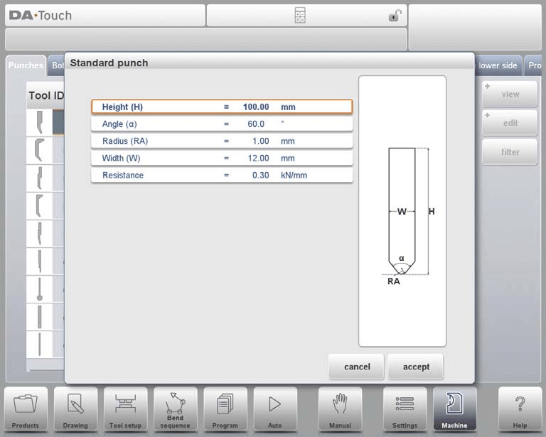
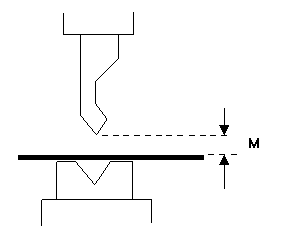
Height: The height the tool. Important: this height value will be used in the bend depth calculation.
Angle: The angle of the punch tip.
Radius: The radius of the punch tip. This value will be used as inner radius of the bend to make when this radius value is bigger than the inner radius as will result from the bending process.
Width: The width of the tool to program.
Resistance: Maximum allowable force on the tool.
Drawing orientation of the punch on the screen
In the DELEM DA-66T Machine Mode, the punch is displayed with its right-hand side as the back gauge side. The bottom point of the punch aligns with the center line of the press brake shape. To create a tool drawing, simply input the typical angle and line length values. You can use the available touch drawing tools, similar to the product drawing method, to complete the punch profile.
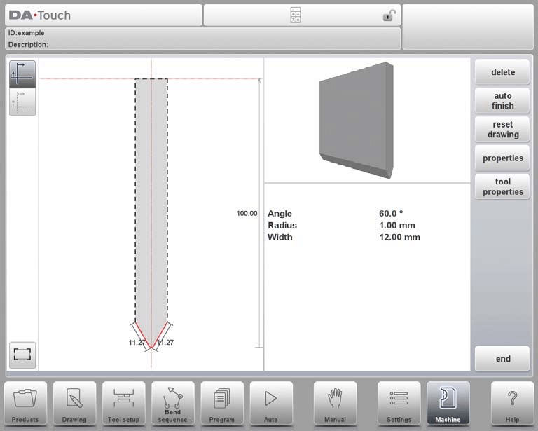
Following functions are available while drawing:
Delete Line: To delete a line segment.
Change Height: To change the height dimension of the tool.
Auto Finish: Finishing the tool outline to the top of the tool automatically.
Reset Drawing: To reset the programmed drawing of the tool till the basic, initial shape.
Properties: To change the specific properties of the line or angle, add or remove a radius, change the length, etc. It is e.g. possible to add a radius in the outline of the tool.
Tool Properties: To change the generic tool data and description.
Description: A name or description of this tool. The maximum length is 25 characters. The description is listed in the tool overview of the library.
Resistance: Maximum allowable force on the tool.
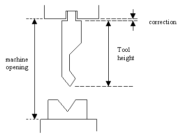
Support type: Switch parameter, to account for differently mounted punches. The control makes a distinction between two settings, ‘head mounted’ and ‘shoulder mounted’.
- 0 = shoulder mounted (default setting)
- 1 = head mounted

In DELEM DA-66T Machine Mode, the Y-axis position is determined based on the selected mounting option. When ‘shoulder mounted’ is chosen, the Y-axis is calculated using the standard tool height as the default setting. Alternatively, if ‘head mounted’ is selected, the Y-axis computation includes a specific correction.
Edit punch drawing
To edit an existing tool, tap the tool in the library. The tool appears on the screen and can be edited with the drawing facilities.
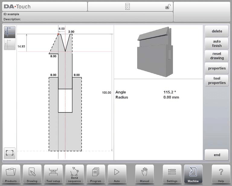
Hem Bend Punch

In the DELEM DA-66T Machine Mode, programming punches is a critical step for precise metalworking results. Here’s a simplified guide to the key parameters you need to configure:
Height: Enter the total height of the tool. This value is crucial as it affects the bend depth calculations during operations.
Hemming Width: Set the specific width of the tool you wish to program for accurate hemming processes.
Hemming Load Opening: Program the opening position of the punch, which is used for inserting the product for hemming specific bends. Ensure this accounts for twice the sheet thickness to accommodate your material.
Hemming Resistance: Define the maximum allowable force on the tool during the hemming process to prevent damage or overloading.
Once these values are entered, you can create a tool drawing using the available drawing features. This involves inputting angle and line length values. The Touch drawing tools can assist, similar to how product drawings are handled.
By setting these parameters accurately, you ensure the DELEM DA-66T operates efficiently and effectively in your production processes.
Air + Hem Bend Punch

Height: The total height of the tool, crucial for calculating bend depth.
Angle: The angle of the punch tip that dictates the shape and angle of the resulting bend.
Radius: The punch tip’s radius, used as the inner radius for bending. It is critical when this radius exceeds the inner radius produced during bending.
Width: Specifies the tool’s width necessary for programming the punch.
Resistance: Indicates the maximum force the tool can withstand during operation.
Hemming Height: The punch’s height used specifically for moving down during hemming functions.
Hemming Width: The width part of the punch that lays in the product during hemming actions.
Hemming Load Opening: This position allows you to easily insert your product for specific bending tasks. The system automatically adjusts the opening to account for twice the sheet thickness, ensuring precision in your operations.

Hemming resistance: Maximum allowable force on the tool during hemming.
After inputting the standard values, you can easily create a tool profile using the drawing features. This involves entering angles and line lengths. Additionally, touch-based drawing tools are available, similar to those used in product drawing methods.

Big Radius Punch
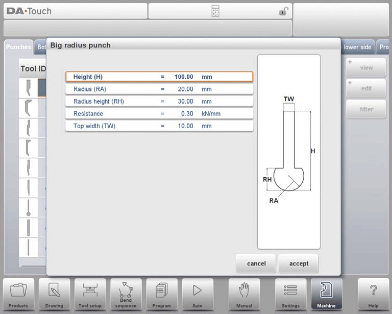
In the DELEM DA-66T Machine Mode, programming punches involves specifying several key parameters that define the punch tool’s characteristics. Here’s a simplified overview:
Height: This is the total height of the punch tool, crucial for calculating the bend depth.
Radius: Refers to the tip radius of the punch, which affects the bending operation.
Radius Height: The vertical dimension of the large radius section on special punches, as shown in the tool’s basic data display.
Top Width: Defines the width of the punch at its uppermost part.
Resistance: The maximum force the tool can withstand during the bending process.
Once these parameters are entered, you can use the system’s drawing tools to visualize and refine the tool profile. This involves inputting angles and line lengths to create the desired punch profile. Additionally, touch drawing tools are available, similar to those used in product drawing methods, to assist in fine-tuning the tool design.

Programming of Bottom Dies
In this section, you can program the bottom dies for the machine. You have the option to add new dies, edit existing ones, or delete them as needed.
View
In the main interface of DELEM DA-66T Machine Mode, you’ll find a list of available dies. The View function allows you to select different viewing options. Besides the default Expanded view, there’s also a Graphical view available.
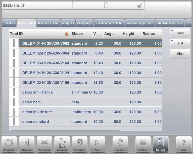
Graphical directory
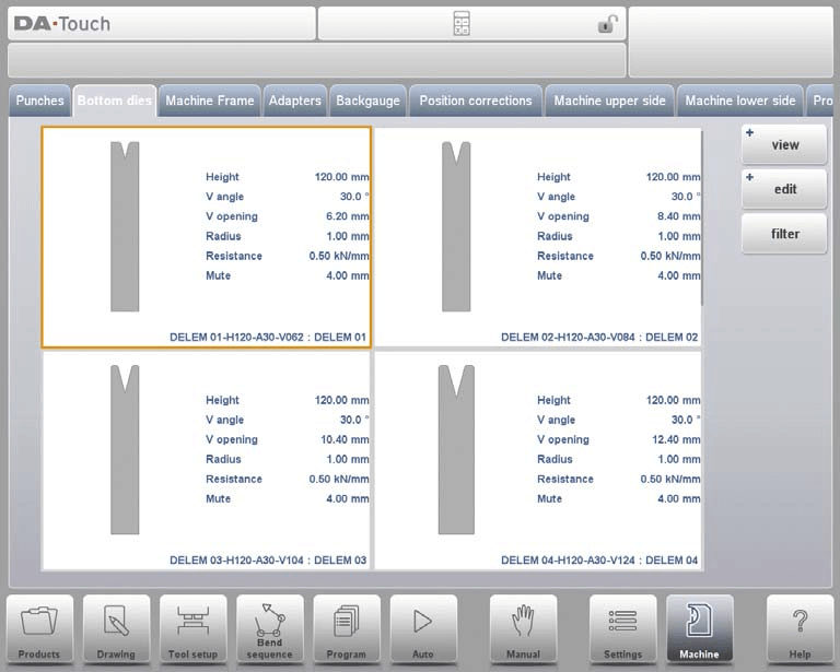
In Graphical the geometry of the tools is shown as well as the main properties. To program a new die, tap Edit in the library and subsequently use New.

Create a New Die
When programming punches in the DELEM DA-66T Machine Mode, here’s a simplified guide for creating a new tool:

- Access the Die Library:
- Tap on ‘Edit’ and then select ‘New’ to start creating a new tool.
- Tool Shape Selection:
- Choose from the available basic die shapes, depending on the die action needed:
- Standard Die: Ideal for air bending and basic bottoming.
- Hem Bend Die: Crafted for specific hem bends with a flat top.
- Inside Hem Bend Die: Used for both air bends and hem functions.
- Air + Hem Bend U Die: Combines features for air bends and specific hem functions.
- Multi-V Die: Suitable for dies with multiple V or U openings.
- Choose from the available basic die shapes, depending on the die action needed:
- Tool Identification (ID):
- Assign a unique name or number (up to 25 characters) to identify the tool. This can include both letters and numbers.
- Finalize Tool Creation:
- Press ‘Accept’ to proceed. A pop-up window will appear, prompting you to input the initial dimensions and properties of the tool.
This streamlined process ensures accurate tool creation for efficient machine operations in the DELEM DA-66T Machine Mode.
Standard Die
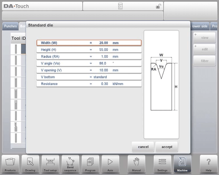
Width: The width of the tool to program.
Height: The total height of the tool. Important: this height value will be used in the bend depth calculation.
Radius: The radius of the edges of the V-opening.
V angle: The angle of the die.
V opening: The V-opening of the die.
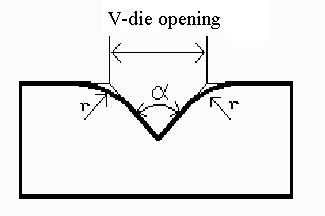
The width V is the distance between the touching lines crossing.
V bottom: Here with the different possible bottoms inside the V opening can be defined.
• Standard is a sharp angle in the bottom of the die.
• Round is a die bottom with a radius to be programmed with the parameter ‘Inside radius’.
• Flat is a flat die bottom with a certain dimension to be set with the parameter ‘Bottom width’.
Resistance: Maximum allowable force on the tool.
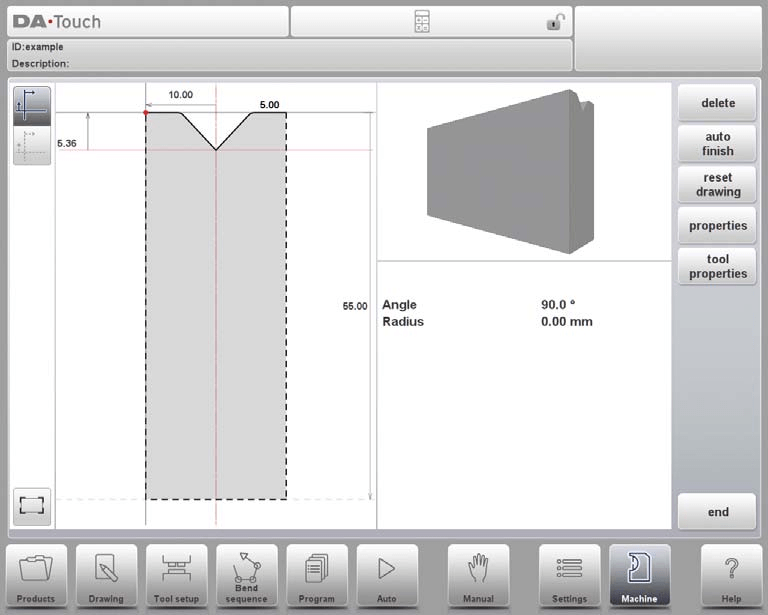
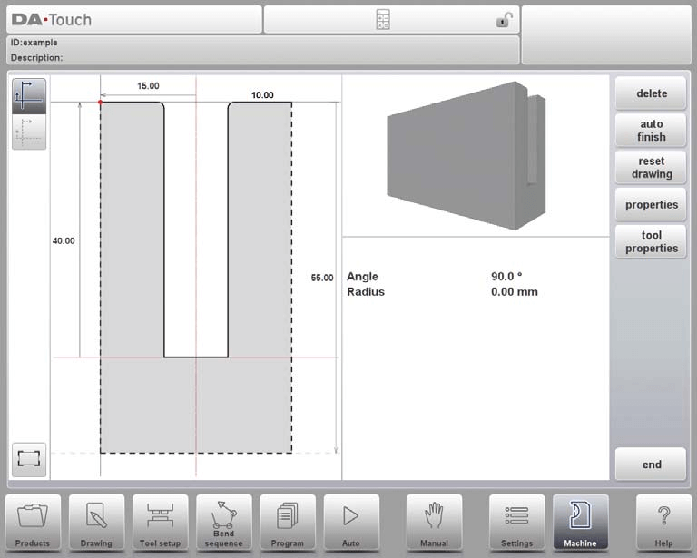
In the DELEM DA-66T Machine Mode, understanding how tools are oriented on the screen is crucial. The die’s right-hand side aligns with the back gauge, and the V-opening’s midpoint aligns with the press brake’s center line, ensuring precision.
Creating a Tool Drawing:
- Input Values: Start by entering typical angle and line length values.
- Drawing Tools: Use the drawing facilities, similar to the product drawing method, to finalize the tool profile.
Mounting point
The mounting point, marked by a triangle arrow, indicates where the die should be connected and positioned on the table or within an adapter. This feature ensures accuracy whether the die is positioned normally or turned, with separate mounting points available for each orientation.
Additionally, mounting points are also present in adapters and on the table itself. If the mounting point function is not enabled, the indicator will not be visible. Proper use of this feature in DELEM DA-66T Machine Mode enhances the precision and efficiency of punch programming, crucial for optimized metalworking outcomes.
Following functions are available while drawing:
Delete Line: Easily remove unwanted line segments from your tool drawing.
Change Height: Adjust the height dimension of tools to fit specific requirements.
Auto Finish: Automatically complete the tool outline up to the top of the tool.
Reset Drawing: Quickly revert drawings to their basic, initial shape for fresh starts.
Properties: Modify specific line or angle properties, including adding/removing radii and changing lengths.
Tool Properties: Update the general data and description of tools for better organization.

Description: Provide or edit a concise name for tools (max 25 characters) for easy identification in the tool library.
Resistance: Define the maximum allowable force the tool can withstand.
X-safe: Utilize calculated safety zones to prevent collisions, crucial when using an R-axis.
X-SAFE = FS + ½ V in which: FS = flat section on the back side of the V-grove. V = opening value. In this formula also a small additional safety value (0.5 mm) has been added.
Mute: Set muting distances to control speed changes above the workpiece.
2nd X-safe: Use additional safety zones for complex dies, ensuring protection even in varied tool positions.

Edit Die Drawing: Tap and modify existing tools directly from the library using intuitive drawing tools.
These functionalities are integral to achieving precision and safety in the DELEM DA-66T Machine Mode. By leveraging these features, users can ensure efficient and accurate punch programming, optimizing tool performance and longevity.
Hem Bend Die

Height: The total height of the tool. Important: this height value will be used in the bend depth calculation.
Hemming width: The width of the tool to program.
Hemming resistance: Maximum allowable force on the tool during hemming. Insights into the programming of hem bend dies.
After entering these typical values you can create the tool drawing with the drawing facilities. Drawing a tool profile is done by entering angle values and line length values.
Inside Hem Bend Die
Height: The total height of the tool.
Radius and V-Angle: These define the edges and angle of the V-opening, influencing the tool’s bending capacity and style.
V-Opening: Determines the die’s opening size, affecting material placement and final bend results.
V-Bottom Options: Choose between ‘Standard’ (sharp angle), ‘Round’ (radius defined by ‘Inside radius’), and ‘Flat’ (dimension set with ‘Bottom width’) to select the die bottom type based on your bending needs.
Resistance: Maximum allowable force on the tool.
Upper and Lower Parts: Define the dimensions of the die’s upper and lower sections, including widths and heights, which are crucial for precise bending and hemming actions.
Hemming Specifications: Includes ‘Upper hemming width’, ‘Hemming load opening’, ‘Hemming resistance’, and ‘Lower hemming width’, all of which are vital for successfully executing hemming operations.
Inside Hemming Die Types: Select from options like ‘Spring Opened’, ‘Open & Locked’, and ‘Normally Closed’, each offering different operational modes for customized bending and hemming strategies.
By configuring these parameters, you can create precision tool profiles using DELEM DA-66T’s drawing facilities. These settings are vital for optimizing performance and ensuring precise metalwork operations, embodying the efficiency and precision of DELEM DA-66T Machine Mode.
Air + Hem Bend U Die
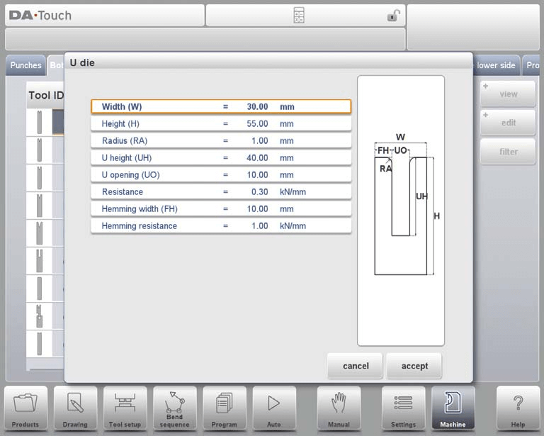
Width: Define the width of the tool you want to program.
Height: Specify the total height of the tool, crucial for calculating the bend depth.
Radius: Set the radius for the edges of the U-opening, aiding in smooth bending.
U Height: Enter the height of the U-opening in the die for accurate shaping.
U Opening: Determine the width of the U-opening of the die.
Resistance: Indicate the maximum force that the tool can withstand.
Hemming Width: Designate the front width of the die, which acts as support during hem bends.
Hemming Resistance: Specify the force limit during hemming operations.
After filling in these values, you can create a tool drawing using the DELEM DA-66T’s drawing facilities. This process involves inputting angles and line lengths, with additional support from touch drawing tools similar to product drawing methods. By carefully setting these parameters, you enhance precision and efficiency in your metalworking tasks.
Multi V die
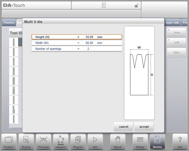
Height: Define the total height of the tool, crucial for calculating the bend depth.
Width: Specify the width of the tool to be programmed.
Number of Openings: Determine the number of V or U openings in the tool.
Opening Properties: After selecting the V or U opening, set specific tool properties, including resistance.
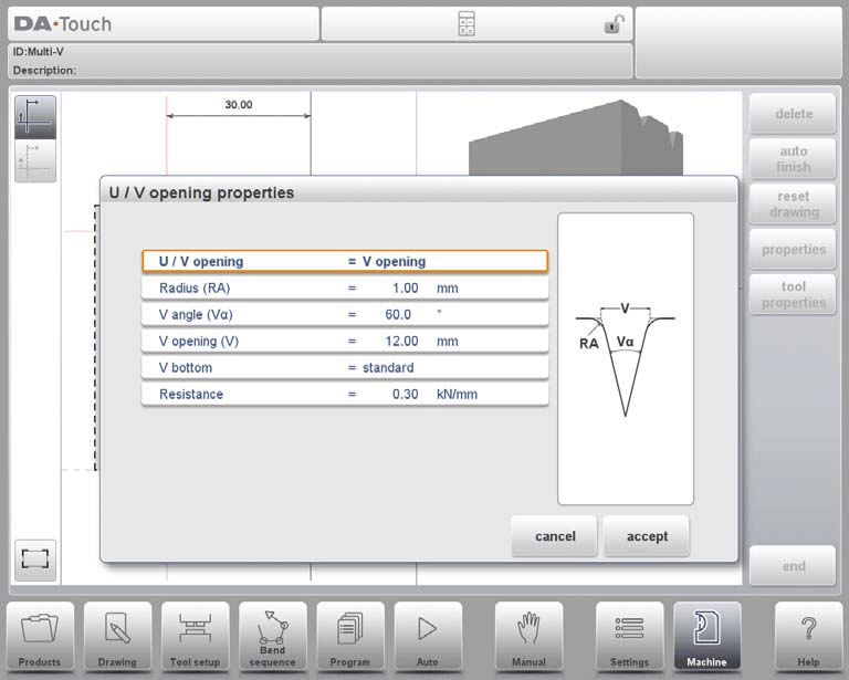
Type of Opening: Choose between V or U opening types.
Radius: Set the edge radius for V-openings, which influences the bend quality.
V Angle: Define the angle of the die for accurate bending operations.
V Opening: Specify the V-opening dimensions of the die.
V Bottom: Choose the bottom type inside the V opening: ‘Standard’ for sharp angles, ‘Round’ for a bottom with a programmed radius, or ‘Flat’ with a defined width.
Resistance: Enter the maximum allowable force for each opening if different. If uniform, simply use the value under Tool Properties.
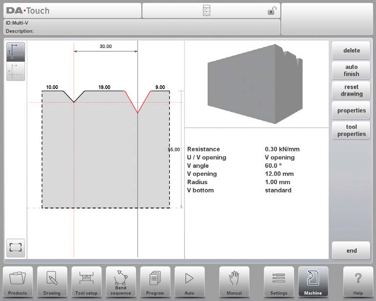
Once these values are set, you can create a detailed tool drawing using the integrated drawing tools, where angles and line lengths facilitate precise tool design.
Vario V die (only available if a Vario-V system is present)
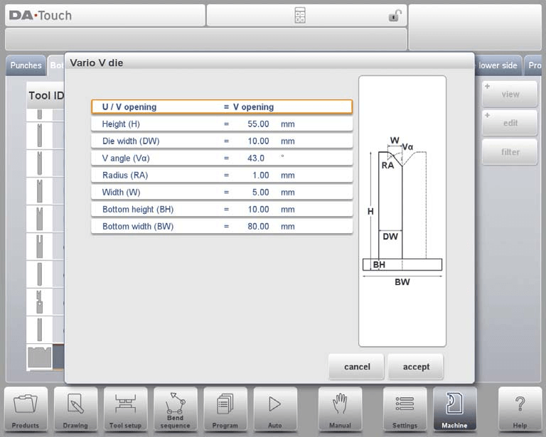
In the DELEM DA-66T Machine Mode, programming punches involves setting specific parameters to ensure precision in bending operations:
U/V Opening: Determine the type and size of the V or U opening.
Height: Total tool height, crucial for calculating bend depth, includes the bottom part in Vario V dies.
Die Width: Width of a single Vario V side.
V Angle: Half of the V angle, important for shaping bends.
Radius: Edge radius of the U or V opening.
Bottom Dimensions: Specify the height and width of the bottom part of the die.
To draw tool profiles, enter angle and line length values.
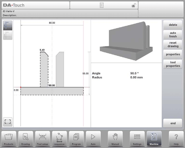
Utilize touch drawing tools like in product drawing methods.
Define tool properties such as name (up to 25 characters), resistance, and safety measures like X-safety offset and muting distance.
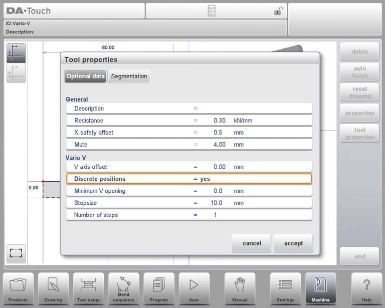
For Vario-V systems, configure V axis offset, discrete positions, minimum V opening, stepsize, and the number of steps.
Machine Frame
In the DELEM DA-66T Machine Mode, precise punch programming is essential for optimizing operations. Here’s a simplified guide:
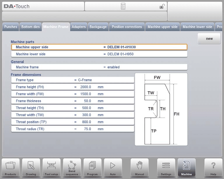
Machine Parts Selection: Select and set active geometries for the upper and lower beams and side frames.
Machine Sides: Choose the relevant machine upper and lower sides using the Filter View for accurate parts selection.
Machine ID: Assign a unique ID for each machine to ensure correct program loading and management.
Frame Settings: Configure side frame dimensions like height, width, thickness, and select frame type, either C-frame or O-frame.
C-frame Contour Editor
Using the contour editor in DELEM DA-66T Machine Mode, you can draw detailed C-frame shapes. Start with a basic shape and customize by adding radii between and within lines.

This graphical approach replaces traditional parameterized frame programming, allowing precise customization.

Frequently Asked Questions(FAQ)
How can I effectively program a hem bend punch in DELEM DA-66T Machine Mode?
To program a hem bend punch in DELEM DA-66T Machine Mode, select the hem bend option within the punch parameters, and input the specific bending angles and radii required for your operation. Ensure that these settings align with your material specifications for optimal results.
What should I consider when selecting punch parameters in the DELEM DA-66T Machine Mode?
Always consider the material thickness and type when inputting punch parameters. This will affect the punch force and angle, ensuring accuracy and preventing tool wear or damage.
Can I save custom punch configurations in DELEM DA-66T Machine Mode?
Yes, after programming a custom punch, save the configuration in the punch library for easy access upon future use. This capability enhances efficiency when switching between different production runs.
Conclusion
In conclusion, the programming of punches in the DELEM DA-66T Machine Mode requires a thorough understanding of each step to ensure accuracy and efficiency. By mastering the processes of viewing, creating, and configuring different types of punches such as standard, hem bend, air + hem bend, and big radius punches, operators can significantly enhance the performance and output quality of their press brake machines.
As your next step, ensure your DELEM DA-66T is regularly updated and maintained according to the guidelines provided in this documentation. For personalized assistance, additional resources, or to address any specific queries, feel free to contact our expert team at HARSLE. We are here to support your journey towards optimal machine operation.


