


If you’re trying to master the DELEM DA-58T machine mode for tool programming, you’re in the right spot.
In this guide, I’ll walk you through the essentials of programming tools on the DELEM DA-58T machine mode, giving you a clear understanding of how to create, manage, and optimize punches and dies. Whether you’re a novice operator or looking to enhance your proficiency, this article will provide you with the insights needed to effectively utilize this powerful tool. By the end of this guide, you’ll be equipped to maximize the efficiency and precision of your operations using the DELEM DA-58T machine mode.
Introduction

By tapping the navigation button Machine the control is switched to Machine mode.
In DELEM DA-58T Machine Mode, accessible through the navigation panel, you can configure machine characteristics and settings that impact calculations and behavior. The settings are organized into several tabs. To navigate, simply tap and select the desired tab—horizontal dragging allows you to view all tabs.
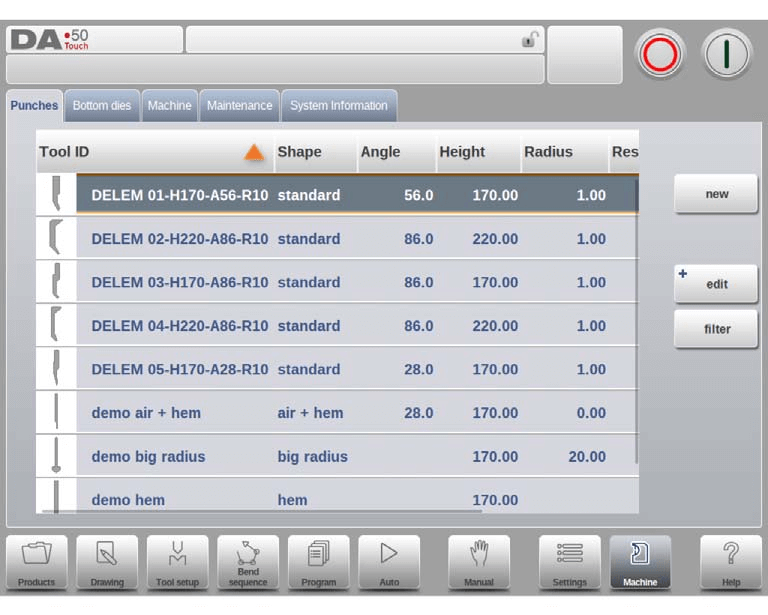
Programming of Punches
Within the DELEM DA-58T Machine Mode, you can program punches by adding new ones, editing existing ones, or deleting them.

Create a new punch
To program tools in the DELEM DA-58T Machine Mode, start by tapping “New” in the library to create a new punch. Utilize the control’s programming and drawing features to define the punch profile.

Begin by programming the punch’s basic shape and ID. Next, use the wizard to program shape details.
Shape: Select a basic punch shape that matches your required punch action. Options include:
- Standard Punch: Used for air bending and basic bottoming.
- Hem Bend Punch: Features a flat bottom for specific hem bends.
- Air + Hem Bend Punch: Suitable for normal air bends and hem functions.
- Big Radius Punch: Designed for large radius bends.
ID: Assign a unique name or number, up to 25 alphanumeric characters, to identify the tool. Once finished, tap “Accept” to move on to entering tool data parameters. A pop-up will prompt you to enter the initial dimensions of the tool, with parameters varying based on the basic shape selected.
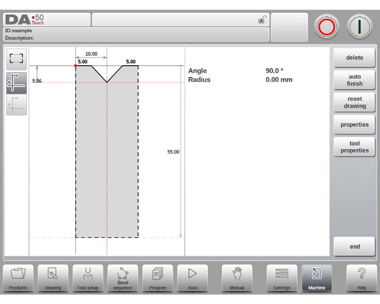
Standard punch
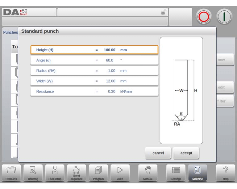
- Height: The height the tool. Important: this height value will be used in the bend depth calculation.
- Angle: The angle of the punch tip.
- Radius: The radius of the punch tip. This value will be used as inner radius of the bend to make when this radius value is bigger than the inner radius as will result from the bending process.
- Width: The width of the tool to program.
- Resistance: Maximum allowable force on the tool.
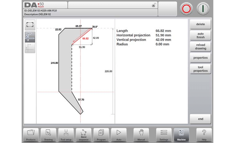
Drawing orientation of the punch on the screen
To program tools on the DELEM DA-58T Machine Mode, start by understanding the drawing orientation of the punch on the screen. The right-hand side represents the back gauge side, with the punch’s bottom point aligned with the press brake’s center line.
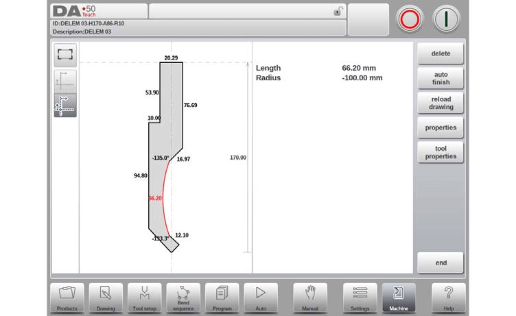
Drawing
After inputting typical values, you can create the tool drawing using the available drawing facilities. This involves entering angle and line length values, similar to the method used in product drawing, and utilizing the Touch drawing tools for precision.
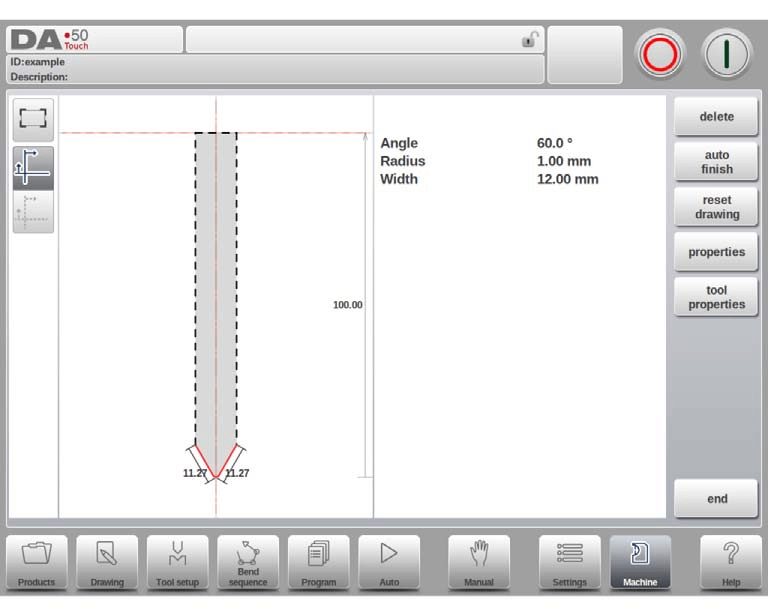
When programming tools on the DELEM DA-58T Machine Mode, several functions are available to assist in creating precise tool outlines:
- Delete Line: Remove any unwanted line segment from your tool drawing.
- Auto Finish: Automatically complete the tool outline up to the top of the tool.
- Reset Drawing: Revert your tool drawing to its initial, basic shape when creating a new punch.
- Reload Drawing: Restore the tool drawing to its original form when modifying an existing punch.
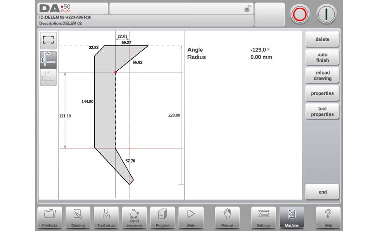
- Properties: Modify line or angle properties, such as adding/removing a radius or changing length.
- Tool Properties: Adjust the general data and description of the tool.
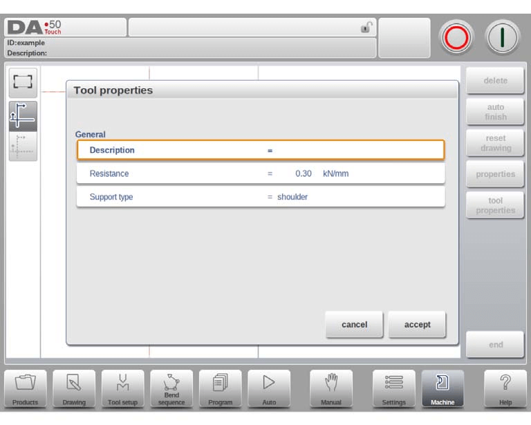
- Description: Edit the tool’s name or description, up to 25 characters, which appears in the tool library overview.
- Resistance: Specify the maximum allowable force on the tool.
- Support type: Adjust for different mounting settings of punches to ensure accuracy; options include shoulder mounted (default) or head mounted.
- 0 = shoulder mounted (default setting)
- 1 = head mounted
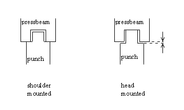
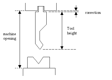
If ‘shoulder mounted’ is chosen, the Y-axis position is calculated from the standard tool height. This is the default setting.
If ‘head mounted’ is chosen, a correction is made for Y-axis computation
- Edit punch drawing: To edit an existing tool, tap the tool in the library. The tool appears on the screen and can be edited with the drawing facilities.
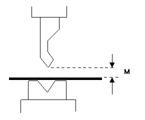
Hem bend punch
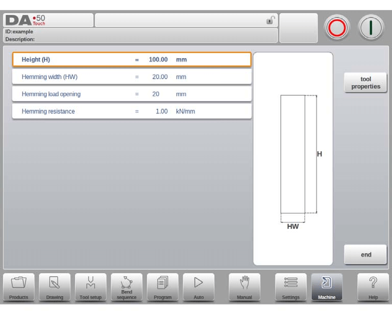
- Height: Tool’s total height, key for bend depth calculation.
- Hemming Width: Programmed tool width for hemming.
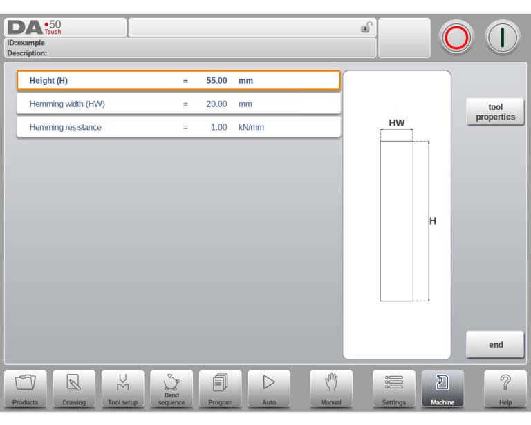
- Hemming Load Opening: Punch opening position, considering twice the sheet thickness.
- Hemming Resistance: Maximum force allowed during hemming.
Air + hem bend punch
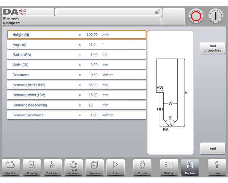
- Height: Total height of the tool, crucial for calculating bend depth.
- Angle: Angle of the punch tip.
- Radius: Radius of the punch tip, used as the inner radius for bending when larger than the process-derived radius.
- Width: Width of the tool being programmed.
- Resistance: Maximum allowable force on the tool.
- Hemming Height: Height of the punch used during hemming.
- Hemming Width: Width of the punch part where the product rests during hemming.
- Hemming Load Opening: Program an opening position considering machine construction and twice the sheet thickness for inserting the product.

- Hemming Resistance: Maximum force allowed on the tool during hemming.
Big radius punch
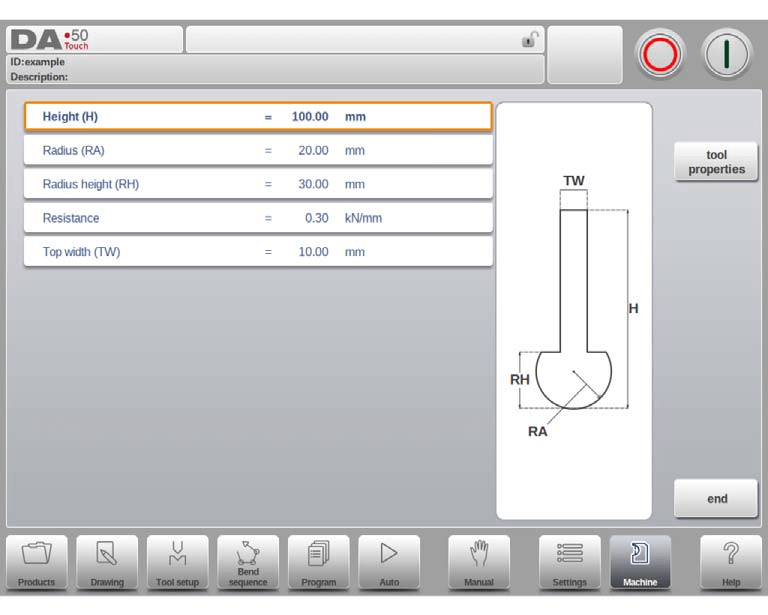
- Height: Specifies the total height of the tool, crucial for calculating bend depth.
- Radius: Defines the radius of the punch tip.
- Radius Height: Represents the height of the large radius section of a special tool, as shown in the basic data drawing onscreen.
- Resistance: Indicates the maximum allowable force on the tool.
- Top Width: Measures the width at the top side of the punch.
Programming of bottom dies
In the DELEM DA-58T Machine Mode, you can program bottom dies, add new ones, edit existing dies, and delete them as needed.
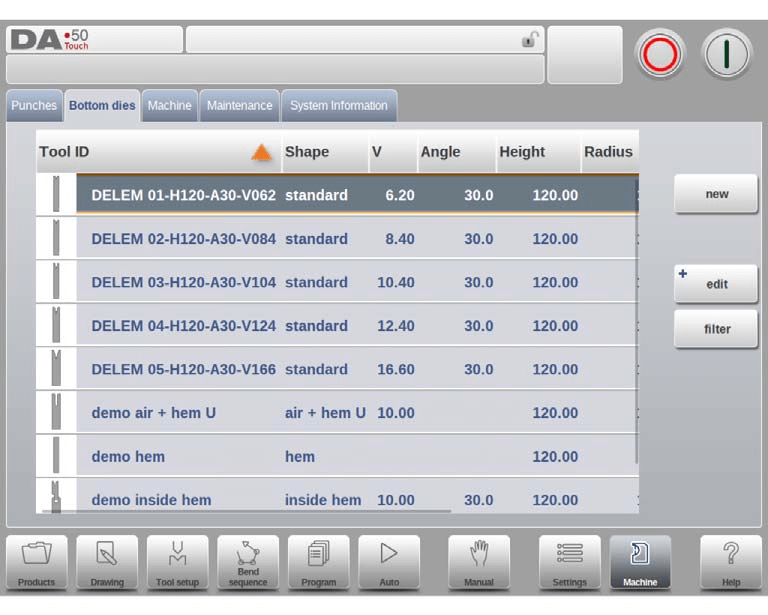
Create a new die
To create a new tool in the DELEM DA-58T Machine Mode, tap “News” in the die library. The control will request the tool shape and tool identification name (ID).
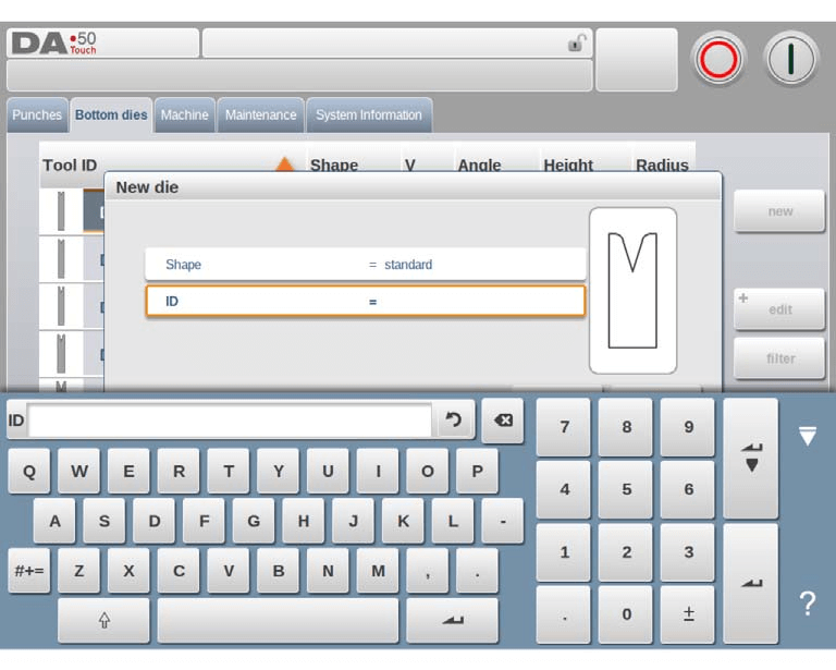
- Shape: Choose from various die shapes for the necessary die action, such as Standard Die for air bending, Hem Bend Die for specific hem bends, Inside Hem Bend Die for air bends, or Air + Hem Bend U Die for specific functions.
- ID: Assign a unique name or number with a maximum of 25 alphanumeric characters to identify the tool.
Once these details are set, tap “Accept” to proceed. A pop-up window will appear, prompting you to input the initial dimensions and tool properties.
Standard die
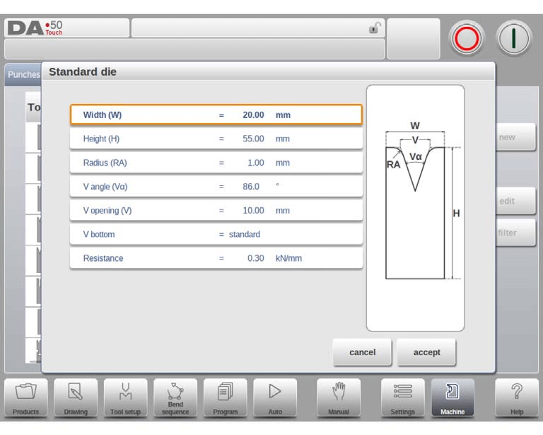
- Width: Specify the tool’s width for programming.
- Height: Enter the total height of the tool, crucial for bend depth calculation.
- Radius: Define the edge radius of the V-opening.
- V Angle: Set the die’s angle.
- V Opening: Specify the V-opening of the die. Note that the width V is the distance between the touching lines crossing.
- V Bottom: Choose the die bottom type:
- Standard: A sharp angle.
- Round: A die bottom with radius, set using the ‘Inside radius’ parameter.
- Flat: A flat bottom, adjusted with the ‘Bottom width’ parameter.
- Resistance: Set the maximum allowable force on the tool.
- Drawing Orientation: The right side of the tool is the back gauge side, with the V-opening’s mid-position aligned to the press brake’s center line.
- Drawing: After inputting the typical values, create a tool drawing by entering angle and line length values. Utilize Touch drawing tools for additional detail.
- Delete Line: Remove a line segment from the tool drawing.
- Change Height: Adjust the height dimension of the tool.
- Auto Finish: Automatically complete the tool outline to the top.
- Reset Drawing: Restore the tool drawing to its basic shape when creating a new die.
- Reload Drawing: Reload the tool drawing to its initial shape when modifying an existing die.
- Properties: Alter specific attributes of the line or angle, such as adding/removing a radius or changing length.
- Tool Properties: Modify generic tool data and descriptions.
- Description: Edit the tool’s name or description (up to 25 characters), which appears in the tool library overview.
- Resistance: Define the maximum allowable force on the tool.
- X-safety Offset: Set a safety zone (minimum X-axis value) to prevent collisions when an R-axis is used.
- Mute: Specify the distance above the sheet where the speed change occurs.
Edit die drawing: To program tools on the DELEM DA-58T Machine Mode, tap a tool in the library to edit its die drawing with the available drawing facilities.
Hem bend die
- Height: This is the total height of the hem bend die. It’s vital for calculating the bend depth accurately.
- Hemming Width: Program the width of the tool as needed for specific operations.
- Hemming Resistance: Monitor and adhere to the maximum allowable force to protect the tool during hemming processes.
Inside hem bend die
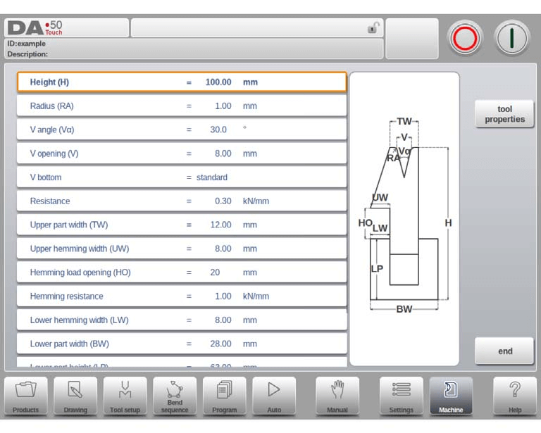
- Height: Indicates tool height, crucial for bend depth calculation.
- Radius: Edges’ radius of the V-opening.
- V Angle: The die’s angle.
- V Opening: Width of the die’s V-opening.
- V Bottom Types:
- Standard: Sharp angle.
- Round: Radius set via ‘Inside radius’.
- Flat: Dimensioned with ‘Bottom width’.
- Resistance: Maximum force the tool can handle.
- Upper Part Width: Width of the die’s upper section.
- Upper Hemming Width: Segment width in the upper part for hemming.
- Hemming Load Opening: Die’s open height for placing products with hem bends.
- Hemming Resistance: Maximum force during the hemming process.
- Lower Hemming Width: Segment width in the lower part for hemming.
- Lower Part Width: Width of the die’s lower section.
- Lower Part Height: Height of the die’s lower section.
- Inside Hemming Die Types:
- Spring Opened: Starts in an open position using an internal spring.
- Open & Locked: Default locked high position for bending; unlock for hemming.
- Normally Closed: Closed low position; activate for hemming.
- Adjust Decompression: Enables hemming load opening addition to decompression distance (spring-opened dies only). Default off.
Air + hem bend U die
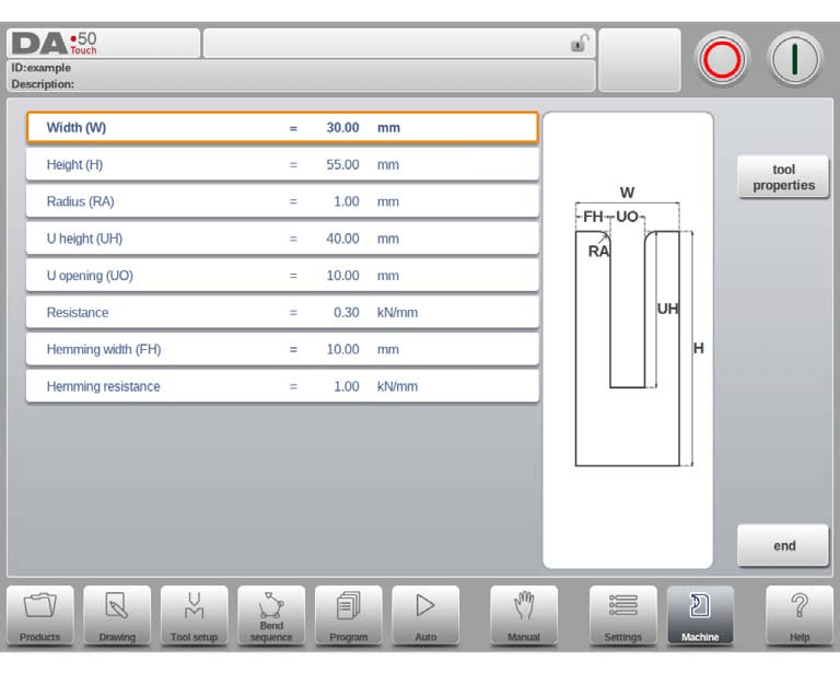
- Width: Program the tool width.
- Height: Total tool height, crucial for bend depth calculations.
- Radius: Edge radius of the U-opening.
- U Height: U-opening height of the die.
- U Opening: U-opening width of the die.
- Resistance: Max allowable force on the tool.
- Hemming Width: Front width for hem bend support.
- Hemming Resistance: Max allowable force during hemming.
Machine
The DELEM DA-58T Machine Mode incorporates backgauge dimensions, including R-axis and X-axis movements, accounting for potential workpiece/backgauge collisions.

- Gauge Positions: Allows up to four gauge positions. When modified, a pop-up window for programming finger dimensions appears.
- Default Lay-On Position: Utilized during automatic bend sequences when X-axis positions exceed limits, preventing manual lay-on level selection. Meaning of lay-on numbers: Lay-on = 1

- Gauge R Offset: This offset adjusts the backgauge position if its placement is against the sheet edge, valid only for gauge position 0, allowing negative values for a lower position.
- Backgauge Finger Dimensions:
- Width: Applicable when an automatic Z-axis is installed.
- Height (FH): Refers to the first finger’s height.
- Length (FL): Refers to the first finger’s length.
- X Position Correction: Adjust the mechanical axis to match the displayed value using a calculated correction parameter (CX).
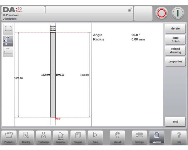
Tap Edit Pressbeam to draw the details of the pressbeam, similar to drawing of tools. Either by tapping and sketching or by giving in the length of sides and pointing the direction of the next side.
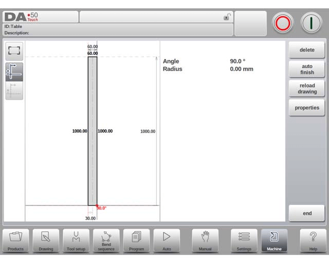
Tap Edit Table to draw the details of the table, similar to drawing of tools. Either by tapping and sketching or by giving in the length of sides and pointing the direction of the next side.
Tap Edit Drawing to make the backgauge drawing appear wherein the dimensions of the backgauge finger can be programmed.
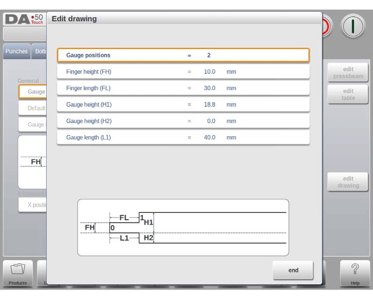
- Additional Gauge Dimensions:
- Height (H1, H3, H4) and Length (L2, L3): Define additional lay-on levels.
- Gauge Base: Defined by height (H2) and length (L1).
Drawing functionality for tools and machine shapes
In DELEM DA-58T Machine Mode, advanced drawing functionality allows users to sketch tools and machine shapes for realism and collision prevention. Users can define shapes segment-by-segment or adjust existing segments for precision.
Key points include:
- Ensure shapes are closed; use auto-finish for assistance.
- Height impacts bending calculations, crucial for results.
- Lines can have radii and snap for alignment.
- Use length, projection, and angle for line programming; the system auto-adjusts these values.
- Help lines measure point distances and enable precise adjustments. They can be toggled off for a clearer view of drawings.
Frequently Asked Questions(FAQ)
How can I optimize the DELEM DA-58T Machine Mode for tool programming?
To optimize tool programming, ensure you fully understand the machine’s interface and make use of the drawing functionality to design precise tool shapes.
Can I program custom tool shapes in DELEM DA-58T Machine Mode?
Yes, the DELEM DA-58T Machine Mode allows for custom tool shape programming. Use the drawing functionality to sketch and adjust segments for your desired tool shapes.
What is the best practice for ensuring accurate punch programming?
Always verify the dimensions and properties of your punches before saving. Utilize the DELEM DA-58T Machine Mode’s collision detection feature to prevent operational errors.
Conclusion
Properly programming tools on the DELEM DA-58T Machine Mode involves creating and editing punches with precision, utilizing drawing functionalities for accurate shape representation, and maintaining regular updates and checks on the system. These steps will enhance the machine’s efficiency and longevity.
Proper setup and maintenance are essential to ensure the longevity and performance of your machine. By following these guidelines, you can minimize downtime and improve production efficiency. For further assistance or detailed support, do not hesitate to contact our team. Additionally, explore our comprehensive documentation for more insights on utilizing DELEM DA-58T to its fullest potential.


