


When it comes to enhancing drawing capabilities, the ESA S640 Integrated CAD system stands out by significantly streamlining the drawing process. If you’re searching for ways to improve accuracy and efficiency in your design workflows, you’re in the right place. In this article, I’ll explain how ESA S640 Integrated CAD empowers you with advanced drawing functions, including both polar and Cartesian settings, that enhance precision and flexibility in drafting. Whether you’re aiming to refine your drawing techniques or optimize your workflow, this guide will provide you with the insights needed to maximize the potential of your CAD system. Let’s delve into the ways this powerful tool can elevate your design process and meet your specific requirements.
Understanding the Drawing Function in ESA S640 Integrated CAD
The drawing function in ESA S640 Integrated CAD operates by tracing line segments based on user-entered data. This tool provides operators with the option to enter data in either a polar or Cartesian format, enhancing flexibility. The use of the polar format is highly recommended for a more user-friendly setup, allowing for easier adjustments and modifications.
Setting Up Polar and Cartesian Formats
How to Define Sections Using Polar Settings
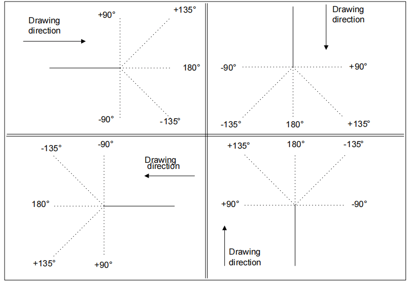
Understanding the polar setting of drawing data is crucial. This allows you to define the sections that make up your drawing through a set of data including the length of the side and the angle compared to the following side. This setup is particularly useful for creating precise and intricate drawings with minimal effort.
How to Use Cartesian Settings for Precision
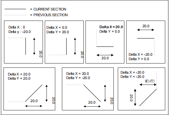
The Cartesian setting is another powerful feature of ESA S640 Integrated CAD. It enables users to define sections with a pair of coordinates that mark the difference between the beginning and end of a segment. This relative system is essential for situations where exact spatial positioning is critical, allowing for highly accurate and detailed work.
Navigating the Drawing Page
In order to access the drawing select with a finger the [Ok] button.
The drawing page consists of several windows:
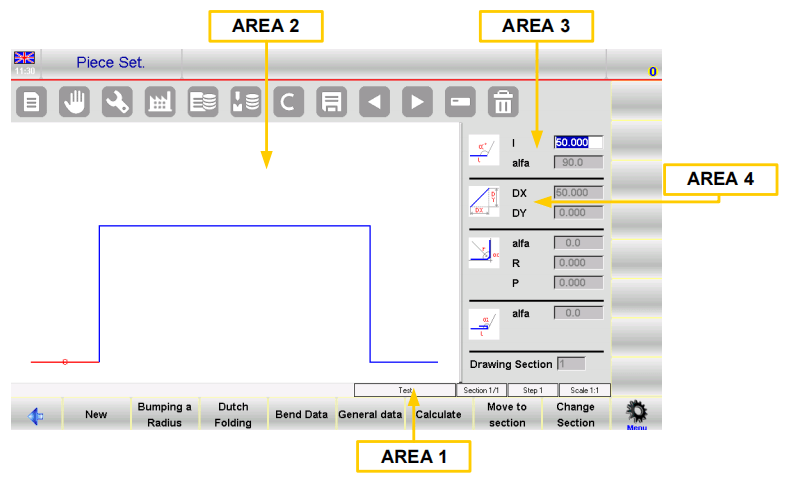
– Area 1 window of the drawing information or the status bar contains:
The name of the program that you are drawing.
The number of the section of the current drawing.
The number of the step of the current drawing.
The scale factor of the drawing.
– Area 2 window of the graphic tracing of the drawing in which the drawing corresponding to the data entered will be displayed.
– Area 3 window of the polar setting of the drawing in which it is possible to enter the data relating to the length of the side to be drawn “l” and the angle compared to the following side “Alpha“.
– Area 4 window of the Cartesian setting of the drawing in which it is possible to enter the Cartesian coordinates “DX” and “DY” which represent the difference between the initial coordinates and the final ones of the length to be drawn.
Entering Data for Drawings
When you access the drawing in Area 2 the first side standard length is automatically drawn. This section will be highlighted in red with a circle around it.
The initial direction of the drawing can be changed by pressing the button [Sub Menu] and selecting the button [Rotation].
The cursor is located in the field “l” in Area 3; there is a standard value in this field. Each value entered must be confirmed by selecting Ok from the soft keyboard.
How to Enter a Drawing in Polar Mode
- Activating Polar Format:
- Ensure the cursor is not in the “l” field of Area 3.
- Press [Sub Menu], then [Polar Format] to activate polar settings.
- Entering Drawing Data:
- Input the length of the side. The side will rescale based on the entered length, moving the cursor to the “alpha” field for angle entry.
- Enter the angle relative to the next length. The current length will display blue, with the subsequent length shown in red.
- Enclose the current section with a circle. Repeat data entry until the drawing is complete.
- Updating Drawing Information:
- If entries exceed window dimensions, the drawing auto-rescales, updating the Area 1 scale factor.
- New lengths increase the current length number, displayed in the “step” field of Area 1.
- Completing the Drawing:
- Set the angle of the final length to zero to complete the drawing.
- Selecting and Changing Drawing Data:
- Use buttons to scroll through drawing data sequentially, navigating between “alpha” and “l” fields.
- To edit data: select the value, enter a new value, press[OK], and the drawing updates accordingly.
- Using Directional Arrows:
- Horizontal/vertical movement via directional keys on the soft keyboard.
- Connect a PS2 or USB keyboard for diagonal movement.
- Existing angles auto-fill the “alpha” field based on directional inputs.
- Deleting and Inserting Lengths:
- Select and delete sections with the delete button; subsequent lengths orient accordingly.
- Use Insert for adding lengths: select 1>> Insert to place before current length, typically extending by 20 mm.
- If inserting is challenging, delete subsequent lengths and restart from the desired insertion point.
How to Use the Cartesian Format
- Activation:
- If polar format is unsuitable, activate Cartesian by pressing [Sub Menu] and [Cartesian Editor] at the desired length.
- The selection shifts to Area 4.
- Defining Segments in Cartesian:
- In the DX field, enter the horizontal axis difference from start to end, then confirm with [Ok].
- In the DY field, enter the vertical axis difference and confirm with [Ok].
- Switching Back to Polar Format:
- Press [Polar Editor] to return to the polar format if needed.
How to Enter Data in Cartesian Mode
When polar settings are insufficient, opt for Cartesian mode for detailed input. Using the Cartesian Editor, enter the horizontal and vertical differences (DX and DY) to outline each segment with precision. If switching back to polar, the transition is seamless, allowing for flexible drawing adjustments as needed.

Optimizing the Drawing Process
Once data entry is complete, ESA S640 Integrated CAD automatically rescales the drawing to fit the window, updating the scale factor. To finalize, set the last length’s angle to zero, indicating completion. Users can efficiently scroll through and edit data to ensure that every drawing meets exact specifications.
ESA S640 Integrated CAD offers powerful drawing capabilities that enhance efficiency and precision. By mastering both polar and Cartesian settings, users can leverage this tool to achieve highly accurate and complex drawings, streamlining the entire design process.
Frequently Asked Questions(FAQ)
How does ESA S640 Integrated CAD enhance the drawing process for beginners?
ESA S640 Integrated CAD simplifies the drawing process by offering intuitive tools and user-friendly interfaces. Beginners can easily navigate its drawing functions, polar settings, and Cartesian modes, making complex tasks more approachable and improving overall efficiency.
Can ESA S640 Integrated CAD handle both polar and Cartesian settings effectively?
Yes, ESA S640 Integrated CAD is designed to seamlessly switch between polar and Cartesian settings, allowing users to select the most suitable method for their specific drawing requirements. This flexibility optimizes workflow and accuracy.
Why should I choose ESA S640 Integrated CAD for professional drawing needs?
ESA S640 Integrated CAD is perfect for professional use due to its advanced drawing features, ease of use, and adaptability to various design standards. It boosts creativity and precision, making it a preferred choice for professionals seeking to enhance their work quality.
Conclusion
In summary, ESA S640 Integrated CAD significantly enhances the drawing process by seamlessly incorporating advanced features such as drawing functions, polar settings, Cartesian settings, and data entry techniques. By using these integrated tools, users can achieve higher precision and efficiency in their drawing tasks, leading to superior design outcomes.
To maximize the benefits of ESA S640 Integrated CAD and enhance your drawing capabilities, it is vital to understand and utilize its comprehensive features effectively. For more detailed support or to inquire further about how ESA S640 Integrated CAD can improve your workflow, don’t hesitate to contact our team. Additionally, we invite you to explore our other documentation for more insights and guidance on effectively using our advanced CAD solutions.


