


If you’re looking to master the ESA S640 Dies Setup for your metalworking operations, you’ve come to the right place. The process might seem complex at first, but I’m here to break it down and make it easier for you. In this article, I’ll guide you through the essential steps needed to efficiently set up dies with the ESA S640 system. By understanding these key components, you’ll enhance your machine’s performance and achieve more precise results. Whether you’re a seasoned professional or just starting out, this guide will provide the valuable insights you need to excel in your projects. Let’s dive into the world of ESA S640 Dies Setup and unlock its full potential.
Dies List
The ESA S640 system provides a comprehensive tools list, allowing users to efficiently manage the available dies and punches. Accessing and managing this list is fundamental to mastering the ESA S640 Dies Setup.
Accessing the Tools List
To view and manage the list of dies, follow these steps:
- Press the button to display the list of punches or dies.

- If the die list initially appears, press again to toggle to punches, and vice versa.
- The left window will display the die list, while the central boxes show data for the selected die, highlighted by the cursor.
- The right window provides a preview of the die currently selected.
- Utilize the scroll bar for a quicker selection when multiple tools are available.

Managing Tools with Function Buttons
The ESA S640 interface includes several function buttons to streamline tool management:
- [New Folder]: Create a new folder to organize and save tools.
- [Find]: Quickly locate a specific tool within the punch or die list.
- [New Drawing]: Initiate a complete drawing of a punch or die.
- [New Default]: Use to design a pre-set die for ease of setup.
- [Insert]: Add the selected punch or die to the work program or specified bend.
Tool Preview and Other Operations
Tool previewing enhances identification and selection. Here’s how to manage previews and perform other operations:
- To disable or enable the tool preview, access the menu and select the 4>> Preview item.
- Copy a tool by selecting it, accessing the menu, and choosing the 0>> Copy option. Enter a new name for the copied tool and confirm with [Ok].
- Rename tools similarly by accessing the 1>> Rename option from the menu, entering the new name, and confirming.
- To eliminate a tool, select it and press [Ok] following menu access.
- Save all tools to a USB by inserting it into the port and selecting the 2>> Save Tools option from the menu.
- Erase all tools through the 3>> Delete Tools menu option and confirm with [Yes].
Maintaining and Transferring Tool Data
Creating backups and transferring tools are crucial for maintaining an efficient setup:
- Insert a USB containing tool data from Kvara S630-S640 or S560 Touch. View the list, perform operations like copy or delete, and manage these tools from the USB device directly.
- Save tools from USB to NC by inserting the USB, accessing the menu, and selecting 2>> Save tools to transfer to the NC disk, allowing downloads to another numeric control.
By effectively using these features and procedures within the ESA S640 Dies Setup, you can enhance your workflow, minimize errors, and achieve precise configurations quickly. Through mastering the tools list and leveraging the ESA S640’s capabilities, you ensure optimal performance in your operations.
How to Enter a New Die for ESA S640
Step 1: Entering a New Die
Press the button on the ESA S640 interface to display the die list.
If you initially see the list of punches, press the button again to bring up the die list. This will ensure you are working with the correct set of tools.
Select Die Type
Once in the die list, select the desired die type that you wish to configure. You have the option to draw a completely new die or choose a pre-set die with adjustable dimensions. Utilizing pre-set dies can simplify the setup process, especially if the die to be entered resembles any of the proposed types, such as square or overturned T dies.

Drawing the Die
For unique dies not covered by pre-set categories—such as multiple V-dies, square V-dies, or Dutch folding dies—it’s essential to create a complete drawing. This step is crucial for performing anti-collision checks and ensuring accurate bending depth calculations based on the die’s dimension data.
Enter Die Dimensions
To proceed with designing the die, you can either select [New drawing] to create it from scratch or [New default] to use pre-set data. Enter the die’s width and height accurately in the designated fields to ensure precise setup.

Access Drawing Page & Finalization
After entering the dimensions and selecting the die type, proceed to the drawing page to finalize your setup. Depending on the type of die selected, the drawing page may vary. Review your entries and confirm the setup by selecting the [Ok] button. This action will save your settings, completing the ESA S640 Dies Setup process efficiently.
Step 2: Dies to Draw
The dies to draw page is obtained by means of the drawing function
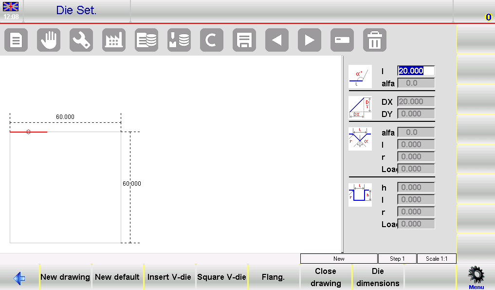
The ESA S640 interface is composed of several windows that facilitate the die drawing process:
- Left-hand Window: This is the main drawing window where the die’s visual representation is created.
- Four Right-hand Windows: These windows are used for data entry and correspond to:
- Polar drawing data
- Cartesian drawing data
- V-die drawing data
- Square die drawing data
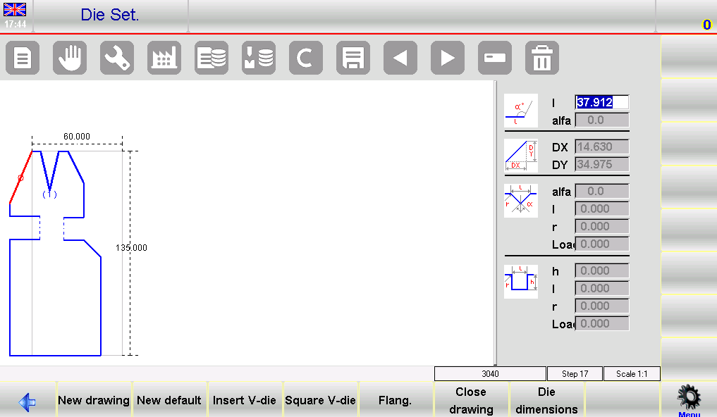
Drawing Conventions
When performing the ESA S640 Dies Setup, it’s important to adhere to certain drawing conventions to ensure accuracy:
- Direction: The die should be drawn in a clockwise direction, with the back-gauges positioned on the right-hand side.
- Line Reference: The marked line represents the proposed line on the drawing page, which serves as a reference for consistency.
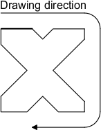
How to Conduct the Drawing
To draw a die accurately, follow these steps:
- Enter Initial Data: Start with the polar drawing data window, entering the initial length l1 by touching the field and confirming with [Ok]. Move to the angle field (α) and input the necessary angle in relation to the next section.
- Define the First V-die:
- Press [Insert V-die] to switch to the V-die data entry window.
- Enter the V-die angle (angle aC1) and confirm with [Ok].
- Input the width “l” of the V-die and confirm.
- Enter the radius R and the V-die load, confirming each entry with [Ok].
- Once completed, the V-die will be drawn, and the system will move to the next segment length.
- Continuing with Sections: Repeat the process for each section of the die, entering lengths (e.g. l2, l3) and corresponding angles where applicable. Use the V-die data entry procedure as needed.
- Correcting Entries: If mistakes are made, entries can be corrected using the interface. Navigate among different data points and amend values by moving between length and angle fields using the designated buttons.
- Square V-die Entry: To enter a square V-die:
- Access the square V-die data entry window by pressing [Square V-die] during angle entry.
- Enter depth “h” , width “l” , radius “r” and V-die load, confirming each step.
- The drawing will update with the new data.
- Advanced Configurations: For Dutch folding or pneumatic dies, follow the specific entry procedures detailed in the interface, which involve setting specific length and angle parameters to define specialized die operations.
Saving and Finalizing the Drawing
Once the ESA S640 Dies Setup is complete, save the drawing by pressing the save button, entering a descriptive name for the die, and confirming with [Ok]. Ensure the name is unique, using alphanumeric combinations common in your die catalog for easy identification.
Step 3: Utilizing Pre-set Dies
Leveraging Pre-set Dies for Standard Operations
The ESA S640 system comes equipped with a library of pre-set dies, offering a quick and reliable solution for standard bending tasks. These pre-drawn dies are accompanied by a series of data points that define their shapes, making it straightforward to implement them in your operations.
Modifying Pre-set Die Values
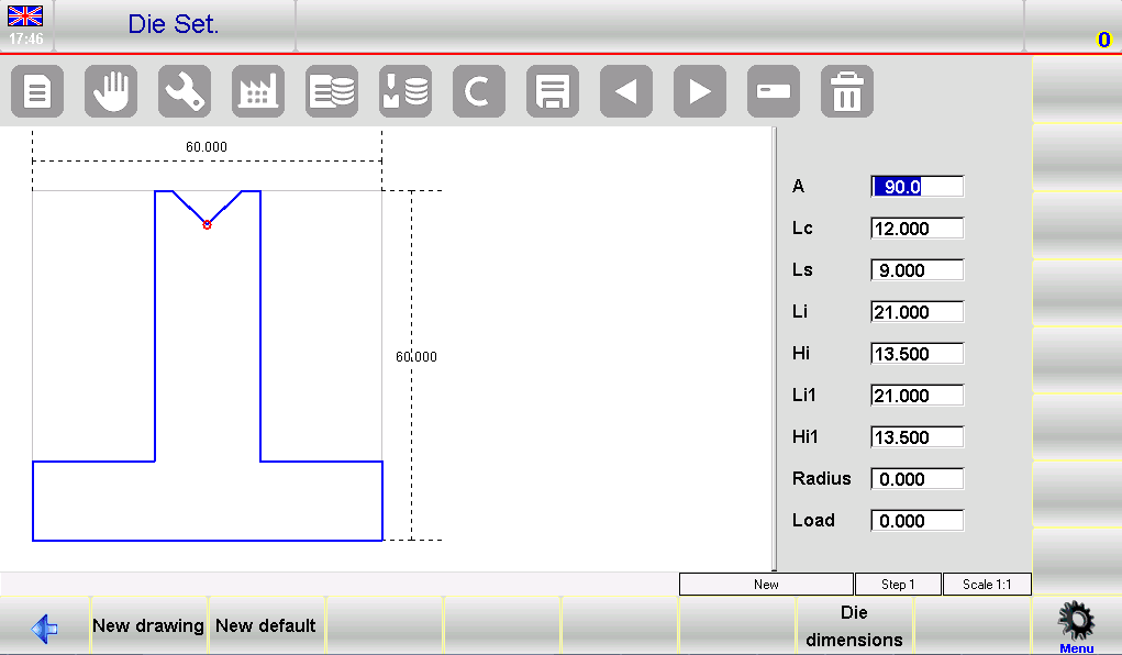
Should you need slight adjustments, the system allows for the modification of any pre-set die values. By altering these values and pressing [Ok], the ESA S640 will automatically re-plot the die drawing to reflect these changes, ensuring your setup is tailored to the specific task requirements.
Saving Customized Setups
Once you have adjusted the pre-set die to suit your needs, it’s essential to save this configuration for future use. To do this, press the save button to store the drawing into the internal memory. A window will appear prompting you to enter the name of the die. Simply touch the field, enter the name, and confirm by selecting the [Ok] button.
Frequently Asked Questions(FAQ)
How can I ensure that my ESA S640 dies are aligned correctly?
Proper alignment of the dies can be achieved by using the alignment tools provided with the ESA S640 system. Follow the on-screen guidance to make fine adjustments, ensuring optimal alignment before proceeding with production.
How frequently should I update my ESA S640 Dies Setup?
It’s advisable to review and update your ESA S640 Dies Setup whenever there’s a change in production requirements or after a significant period, like every six months, to ensure you are using the most efficient and updated settings.
Conclusion
In summary, mastering the ESA S640 Dies Setup involves saving configurations effectively, naming dies descriptively, and confirming the setup for future use. These key steps ensure your press brake machine operates efficiently and consistently, contributing to enhanced precision in your metalworking projects.
For the best results, integrate these practices into your regular maintenance routines to minimize downtime and maximize production efficiency. If you have any questions or need more detailed support, please don’t hesitate to contact our team. Additionally, feel free to browse our other documentation for further insights and guidance on using your equipment to its fullest potential.


