


ESA S875 Graphic Programme is a widely used and intuitive programming mode for press brake operators who need to create bending programs visually and accurately. If you are looking for a clear explanation of how the ESA S875 Graphic Programme works and how to use it effectively, this guide provides a practical and structured answer. This article explains the graphic programming workflow, key parameters, and setup steps required to build reliable bending programs, helping operators reduce programming errors, improve efficiency, and achieve consistent bending results in daily production.
Introduction
Setting up an ESA S875 Graphic Programme is a structured process that enables operators to visually create bending sequences directly on the control system. Graphic programming follows the same initial workflow as numeric programming, but with the added advantage of drawing-based part definition, which improves clarity, accuracy, and process reliability.
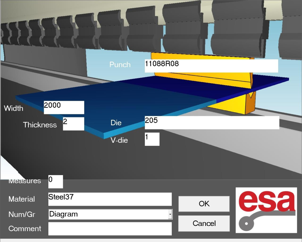
To begin, access the programme data setup mask and select “Graph” in the Num / Gr field. This selection activates the graphic programming environment and allows the system to process geometry-based inputs instead of purely numeric bend data.
Setting the General Data for ESA S875 Graphic Programme
Correct entry of general data is mandatory. Without completing this step, access to the drawing function is restricted by the control system.
Defining Sheet Dimensions and Material Properties
The first step in configuring an ESA S875 Graphic Programme is defining the physical properties of the metal sheet:
- Enter the sheet width to define the working length.
- Enter the sheet thickness, which directly affects bending force and calculations.
- Select the material resistance to be bent.
Material selection is optimized for speed. When the material field is activated, the Materials Table opens automatically, displaying predefined material data. After selection, the material name appears in the programme data, and resistance values are calculated automatically, ensuring consistency throughout the bending process.
Selecting Workstation and Tool Configuration
Once sheet data is entered, tooling and workstation parameters must be defined:
- Specify the workstation if the machine is equipped with multiple stations.
- Select the die to be used; the die must already exist in the system library.
- Define the die cavity number, accounting for multi-cavity dies when applicable.
- Set the die orientation (standard or rotated 180°).
- Select the punch from the punch library.
- Define the punch orientation according to the setup.
- Add optional comments to document special requirements or production notes.
After confirming all general data, the system transitions automatically to the drawing environment.
Understanding the Drawing Window in ESA S875 Graphic Programme
The drawing window is the core workspace for the ESA S875 Graphic Programme. It provides a visual interface that directly represents the part geometry.
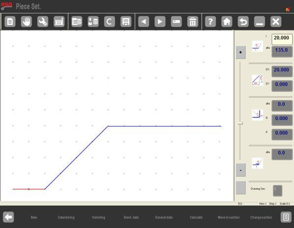
The layout consists of:
- A drawing display area on the left side.
- Four dedicated data input windows on the right side:
- Polar drawing data
- Cartesian drawing data
- Calendering drawing data
- Clinching (squash and close) drawing data
At entry, the system generates an initial red segment with a default length of 20.0 mm, serving as the starting reference for the drawing.
Creating Segments and Angles in Graphic Programming Mode
Entering Segment Lengths
Touching the center of a segment opens the Soft Keyboard, allowing direct numeric input of the desired length. After confirmation, the system prepares the next segment automatically, ensuring a continuous drawing workflow.

Defining Angles and Directions
Angles can be entered in two ways:
- By selecting one of the eight blue directional arrows, which represent standard angles commonly used in bending operations.
- By manually entering the angle value in the Alpha (α) field, enabling full flexibility for non-standard geometries.
Each new segment is created by touching the screen in the intended direction, ensuring intuitive control over part shape.
View Control and Navigation Tools
To maintain accuracy and visibility during complex drawings, the ESA S875 Graphic Programme provides several navigation tools:
- The ZOOM bar allows the operator to enlarge or reduce the view.
- Dragging the drawing area enables repositioning of the part on the screen.
- The CALCULATE function allows repositioning of the machine drawing relative to the part.
These tools are also available during semi-automatic and automatic operation modes, ensuring consistency across all stages of production.
Bend Sequencing and Visualization Options
Bend Sequence Verification
The Bending Sequence function displays the order in which bends must be executed:
- Open the menu and select the item Bending sequence (0).
- Navigate through bends using the directional keys.
This verification step helps identify potential collisions and ensures that the programmed sequence is feasible before production begins.
Color Adjustment and 3D Viewer
For enhanced visualization:
- The Colour Change function allows customization of background and part colors.
- The 3D Viewer displays the part in three dimensions, providing a clearer understanding of final geometry and bend orientation.
These tools significantly reduce interpretation errors during setup.
Drawing Advanced Operations: Calendering and Clinching
Calendering Operations
Calendering can be integrated directly into the drawing process. The system requires straight sections before and after the calendered area to maintain geometric continuity. By entering calendering angle, radius, and pitch, the system automatically generates the curved profile while preserving dimensional accuracy.
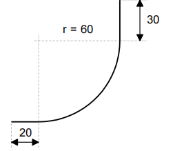
The cursor is located in Field I of the window for the polar setting of the drawing data:
– Enter the length corresponding to the first section of the piece to be drawn (20.0) in Field I.
– Press [ENTER].
– Press [Calendering]; the window of the calendering data will open.
– Enter the desired calendering angle (90.0°) in Field α .
– Press [ENTER].
– Enter the radius of the calendering (60.0) in Field R.
– Press [ENTER].
– Enter the length of the calendering pitch you want to obtain in Field P.
– Press [ENTER], the next section will be drawn in automatic mode; the section that the data refer to will be highlighted.
– Enter the length corresponding to the last section to be drawn (30.0) in Field I (length of the section).
– Press [ENTER], the drawing has now been completed.
Clinching (Squash and Bend)
Clinching operations are defined by activating the Clinching function during drawing. Intermediate angles and segment lengths are entered sequentially, allowing squash and bend operations to be embedded directly into the part geometry.

The cursor is located in Field I of the window of polar setting of the drawing data.
– Enter the length of side L1 to be clinched (30.0) in Field l.
– Press [ENTER].
– Press [Clinching].
– Enter the intermediate clinching angle (e.g.: 45.0°) in the Alpha field.
– Press [ENTER], the next section will be drawn in automatic mode; the section the data refer to will be highlighted.
– Enter the length of the current section (100.0) in Field I.
– Press [ENTER], the cursor will move onto Field α for setting the angle compared to the following section.
– Enter the value of the angle (-90.0°).
– Press [ENTER], the cursor will move onto Field α for setting the length of the section.
– Enter the length of the side (100.0) in Field I.
– Press [ENTER].
– Press [Clinching].
– Enter the intermediate clinching angle (e.g.: 45.0°) in the Alpha field.
– Press [ENTER], the next section will be drawn in automatic mode; the section the data refer to will be highlighted.
– Enter the length of the last section (22.0) in Field I. The drawing has now been completed.
Saving the ESA S875 Graphic Programme
After completing the drawing and verifying all parameters:
- Activate the Save function.
- Enter a unique programme name.
- Confirm to store the programme.
Saving ensures the ESA S875 Graphic Programme can be recalled, edited, or reused for consistent and repeatable production.
Frequently Asked Questions(FAQ)
What is the difference between an ESA S875 Graphic Programme and a Numeric Programme?
An ESA S875 Graphic Programme allows operators to create bending programs by visually drawing the part geometry, while a numeric programme requires manual input of bend parameters only. Graphic programming improves clarity, reduces interpretation errors, and is especially useful for complex parts with multiple bends, calendering, or clinching operations.
Can material data be changed after starting an ESA S875 Graphic Programme?
Yes, material data can be changed, but doing so may affect bending calculations. After updating material resistance in an ESA S875 Graphic Programme, it is recommended to review the drawing and bend sequence to ensure all calculated values remain correct before running the programme.
Is it possible to combine clinching and standard bends in one ESA S875 Graphic Programme?
Yes, the ESA S875 Graphic Programme supports combining clinching (squash and bend) operations with standard bends within the same drawing. Clinching functions can be activated at specific segments, allowing complex forming operations to be programmed in a single graphic programme.
Conclusion
The ESA S875 Graphic Programme offers a practical and visual approach to press brake programming, allowing operators to create accurate bending sequences directly from part drawings. By correctly entering general data, selecting the appropriate tooling, and using the graphic drawing functions, reliable bending programs can be generated efficiently.
Proper use of the ESA S875 Graphic Programme helps reduce programming errors, improve production efficiency, and ensure consistent bending results. For further technical support or detailed guidance on ESA S875 controllers, please explore related resources on the HARSLE website or contact the HARSLE team for professional assistance.


