


Proper ESA S650 Dies Setup is crucial for ensuring accurate and efficient press brake operations. Knowing the key steps in ESA S650 Dies Setup allows operators to quickly configure dies, ensuring consistent bending results and minimizing setup time. In this guide, we will walk you through the essential steps of die installation and alignment, from selecting the right dies to securing them in place, all while maintaining machine safety and performance. By mastering these steps, you can optimize your workflow and achieve high-quality results every time.
Understanding the ESA S650 Dies Setup Interface
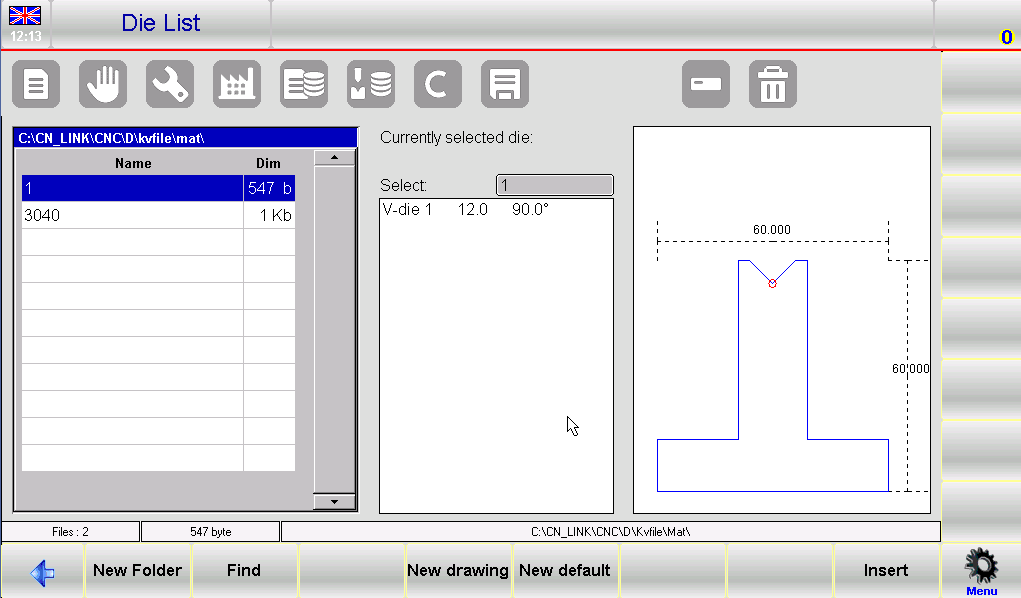
Before you begin any ESA S650 Dies Setup, it’s important to familiarize yourself with the on-screen layout. The interface is divided into three main areas. The left window displays the die list, showing all available dies stored in the system. The central boxes show the detailed data of the die to which the cursor is currently set – this includes dimensions, angle, radius, and load capacity. The right window provides a graphical preview of that same die, which helps with quick visual identification. When your tool library contains many dies, you can use the scroll bar to move through the list faster, saving time during your daily ESA S650 Dies Setup tasks.
Key Function Buttons for Die Management
The following function buttons are essential during your ESA S650 Dies Setup. Each serves a specific purpose:
- [New Folder] – Creates a new folder where you can save and organize your dies by category (e.g., “V-dies”, “Square dies”, “Folding dies”).
- [Find] – Searches for a specific tool within the punch or die list. This is extremely useful when you have hundreds of tools.
- [New Drawing] – Opens the full drawing page where you can draw a completely new die from scratch, using polar or Cartesian coordinates.
- [New default] – Uses a pre‑set die with fixed dimensions. This is the quickest way to add standard dies.
- [Insert] – Inserts the selected die directly into your work program or into a specific bend within a program.
Understanding these buttons is the first step toward mastering ESA S650 Dies Setup.
Basic Die Management – Copy, Rename, and Erase
A clean and well‑organized tool library is the foundation of an efficient ESA S650 Dies Setup. Here’s how to manage individual dies step by step.
How to Copy a Die
Copying a die allows you to create a duplicate under a new name. This is useful when you want to modify an existing die slightly without losing the original. Select the die you wish to copy with your finger, then follow these steps:
- Press the menu button (located in the bottom right corner of the interface) to access the options menu.
- Select the 0>> Copy item from the list.
- A new window will appear where you must enter the new tool name. Use a descriptive name, such as “V-die_30mm_copy”.
- Tap [Ok] to confirm. The copied die will now appear in your die list.
How to Rename a Die
If you have a die with an unclear or incorrect name, renaming it helps maintain order. Select the die you wish to rename, then:
- Press the menu button.
- Choose 1>> Rename from the menu.
- Enter the new name in the pop‑up window. You can use numbers and letters – for example, “Square_V_die_20mm”.
- Press [Ok] to save the change.
How to Erase a Die
When a die is no longer needed (e.g., obsolete tooling), you can erase it to reduce clutter. Select the die, then:
- Press the menu button.
- Press [Ok] to confirm the deletion. The selected die will be erased immediately from internal memory. There is no undo, so be certain before confirming.
These basic management operations are performed frequently during any ESA S650 Dies Setup routine.
Backing Up and Restoring Dies During ESA S650 Dies Setup
Protecting your die library is a smart part of any ESA S650 Dies Setup. The system allows you to save all tools to a USB drive and restore them later, which is essential for disaster recovery and for transferring tools between machines.
Save All Tools on USB
To create a complete backup of all dies and punches:
- Insert a formatted USB device with enough free space into the USB port.
- Press the menu button to access the options.
- Select 2>> Save Tools.
- All tools (both dies and punches) will be saved to the USB drive. This operation may take a few seconds depending on the number of tools. Once complete, you have a full backup of your ESA S650 Dies Setup configuration.
Erase All Tools
Use this option with extreme caution. It deletes every die and punch from the internal memory. To perform this:
- Press the menu button.
- Select 3>> Delete Tools.
- A confirmation dialog will appear. Select [Yes] to erase all tools permanently.
Only use this function when you are certain you have a valid USB backup.
Tools List on USB Device and Restoring to NC
You can view and manage tools stored on a USB drive just like the internal list. This is helpful for selecting individual tools from a backup. To restore all tools from USB back to the NC:
- Insert the USB device containing the tools (created by an ESA S630, S640, S560 Touch, or S650 system).
- Press the menu button – the list of punches and dies on USB will be displayed.
- Press the menu button again and select 2>> Save tools.
- All tools (dies and punches) will be copied from the USB external memory to the internal NC disk, overwriting any existing tools with the same names if present.
This restore function is a key part of recovering your ESA S650 Dies Setup after a system failure or when moving to a new control.
Step‑by‑Step Guide to Entering a New Die
Now let’s focus on the most detailed part of your ESA S650 Dies Setup: entering a new die. You have two main options: draw the die completely using the drawing page, or use a pre‑set die with adjustable dimensions.
Accessing the Die Entry Screen
- Press the die list button (usually labeled with a die icon). If the punch list appears instead, press the button again to toggle to the die list.
- Choose the type of die you want to enter – either a completely new drawing or a pre‑set type.
Important note: The die drawing is used for anti‑collision checks on graphically designed workpieces. The bending depth calculation is also based on the die dimensions you enter. If you have difficulty drawing a complex die, you can use a pre‑set die and adapt its dimensions as closely as possible to the real shape. This will still provide reasonable collision detection.
Using a Pre‑Set Die
Pre‑set dies are ideal when your die is similar to one of the proposed types, such as square dies or overturned T dies. To use a pre‑set die:
- Press [New default].
- A window will open requesting the die width and height. Enter these values by tapping on the “width” and “height” fields.
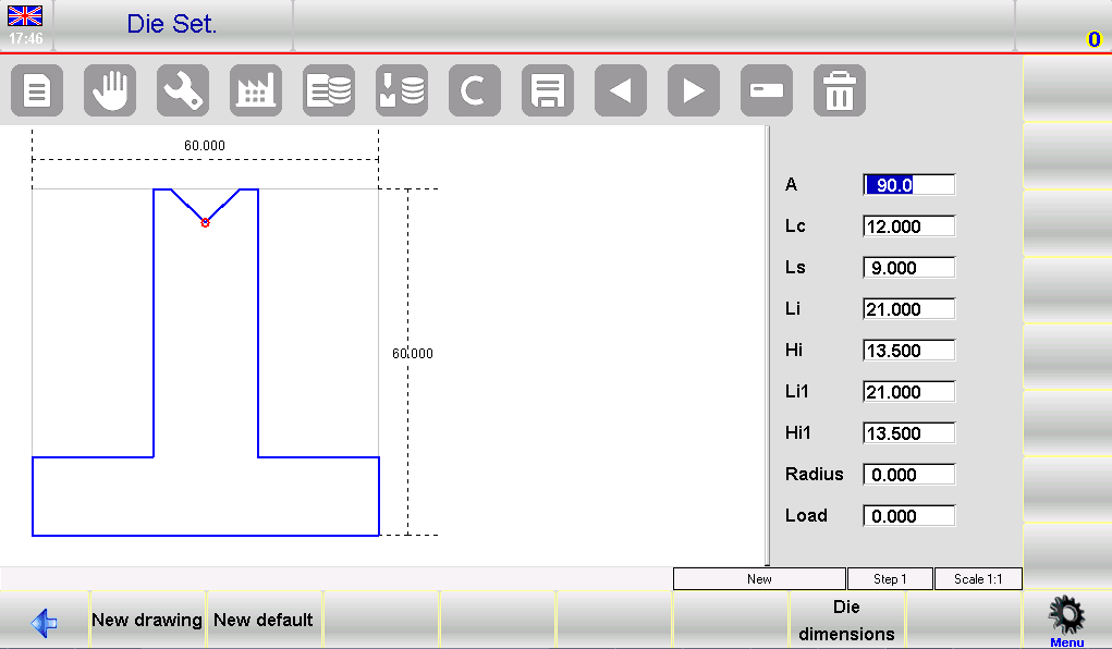
- After confirming, the pre‑drawn die appears along with a series of data fields that characterize its shape. Modify any value – for example, change the V‑opening width or the angle – and the drawing will automatically re‑plot.
- When satisfied, press [Ok] to save.
Using pre‑set dies speeds up your ESA S650 Dies Setup significantly, especially for standard tooling.
Drawing a Die from Scratch
If your die does not match any pre‑set category – for example, a die with multiple V‑steps, a special square V‑die, or a Dutch folding die – you need to use [New drawing].
Drawing Conventions
- Draw the die clockwise. The system expects this direction.
- Remember that the back‑gauges are on the right‑hand side of the die. This affects how the drawing is interpreted for collision checks.
Step‑by‑Step Drawing Process
- Start by entering the first length (l1) in the polar data field labeled “l”. Tap the field, enter the value, then press [Ok].
- The cursor moves to the angle field (α). Enter the angle for the next section relative to the previous one, then press [Ok].
- To insert a V‑die (a recess in the die profile), press [Insert V‑die]. The data entry window switches to V‑die data. Enter:
- V‑die angle (aC1)
- Width of the V‑die (lC1)
- Radius (R) at the bottom of the V
- Load (maximum tons per meter)
- Press [Ok] after each entry. The V‑die will be drawn, and the cursor returns to the polar data window.
- Continue entering lengths and angles alternately. Each length corresponds to a straight segment, and each angle defines the turn to the next segment. The more accurate your measurements, the more correct the drawing will be.
- To correct an incorrect entry, use the previous/next buttons (arrow icons) to move between fields. You can then modify the values directly.
This systematic approach ensures a precise ESA S650 Dies Setup even for complex dies.
Entering a Square V‑Die
Square V‑dies are common in many bending applications. When you are on the angle entry field (α) of the length just before the V‑die:
- Press [Square V‑die].
- Enter the following values in the pop‑up window:
- Depth (h) – how deep the V‑cut goes
- Width (l) – the opening width of the square V
- Radius (r) – the internal radius at the bottom corners
- Load – maximum tons per meter
- Press [Ok] – the square V‑die will be drawn automatically.
Note: The minimum bend angle possible with this die is determined by the entered width and depth. The system calculates this for you.
Entering a Dutch Folding (Hemming) Die
Dutch folding dies (also called hemming dies) allow you to flatten a bend completely. To enter one:
- Draw the open die profile including the recess for the flattening part.
- Move the selection cursor to the vertical line that will act as the folding part.
- Press [Flang.] – that line will appear hatched in the drawing, indicating it is the folding element.
This feature is specific to advanced ESA S650 Dies Setup for hemming operations.
Entering a Pneumatic Dutch Folding Die
Pneumatic dies open and close under air pressure. To define one:
- Draw the profile with 0.001 mm lines for the flattening parts – this simulates the die in a nearly closed position.
- Mark the flattening lines by selecting them and pressing [Flang.] as above.
- After completing the drawing, press [Die dimensions] and enter
1in the “Pneumatic (1=yes 0=no)” field. - Press [Ok]. From this moment, function 2 will be automatically enabled on Dutch folding bends. The ram will change speed earlier to avoid tool collision during fast approach.
This advanced setup ensures safe operation with pneumatic folding dies.
Saving the Die
After finishing your drawing – whether pre‑set or custom – you must save it:
- Press the save button (usually a disk icon or a dedicated function key).
- Enter a name for the die. You can use numbers and letters, for example “V_die_85deg_20mm” or a catalogue code like “DIE-1024”.
- Press [Ok] to save to internal memory. The die will now appear in your die list and is ready for use in programs.
How to Display or Disable the Die Preview
During ESA S650 Dies Setup, you can control whether the tool preview window is shown. The preview is normally enabled, which makes it easier to identify dies visually. However, if you want to save screen space or speed up navigation, you can disable it:
- Press the menu button to access the menu.
- Select the 4>> Preview item.
- The preview is now disabled. Repeat the operation to re‑enable it.
This small customization can make your ESA S650 Dies Setup more comfortable depending on your personal preference.
Frequently Asked Questions (FAQ)
Can I restore a single die from USB without overwriting all existing tools?
The “Save tools” function restores all tools from USB to the NC. However, you can view the USB tool list and manually copy or insert individual dies by selecting them and using the [Insert] button, similar to working with the internal list.
How do I enable or disable the die preview during ESA S650 Dies Setup?
Press the menu button, then select 4>> Preview. If the preview is disabled, repeat the operation to re‑enable it. The preview function is normally on – it helps you visually identify dies.
What should I do if my die drawing won’t save?
Ensure you have entered all required fields (lengths, angles, V‑die data) and that the drawing follows the clockwise convention. Also check that the die name does not contain invalid characters – only numbers and letters are allowed. Then press the save button and enter a valid name.
Conclusion
Completing a successful ESA S650 Dies Setup involves understanding the interface, managing your tool library (copy, rename, erase), backing up and restoring dies via USB, and most importantly – knowing how to enter new dies, whether pre‑set or fully drawn. By following the step‑by‑step drawing conventions for V‑dies, square V‑dies, Dutch folding dies, and pneumatic dies, you can ensure accurate anti‑collision checks and proper bending depth calculations.
Now that you know the key steps, I encourage you to practice with a few sample dies. Build a well‑organized tool library, perform regular USB backups, and refer back to this guide whenever you encounter a new die shape. For further support or advanced parameters (such as pneumatic flattening die support), consult your machine’s parameter manual or contact our technical team.


