


The ESA S650 Punches Setup process is essential for ensuring precise bending performance and safe machine operation. Knowing how to complete ESA S650 Punches Setup easily helps operators achieve accurate alignment, reduce setup time, and avoid common tooling errors.
In this guide, we will walk through the key steps of ESA S650 Punches Setup, including punch installation, positioning, and alignment checks. Whether you are setting up new tooling or adjusting existing punches, following the correct procedures will help you improve efficiency and maintain consistent bending quality.
How to Start ESA S650 Punches Setup for New Punch Entry
Step 1: Accessing the Punch Library
To begin the ESA S650 Punches Setup, operators need to access the punch management interface. Press the punch button on the control system to display the list of available punches. If the die list appears instead, press the button again to switch to the punch list.
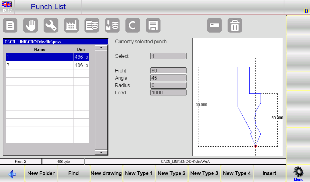
This interface allows you to select existing punches or create a new one, forming the foundation for accurate tooling setup.
Step 2: Choosing the Right Punch Type
When creating a new punch, the system provides multiple options:
- New Drawing: Fully customize and design a punch
- Pre-set Type 1–4: Use standard punch templates with fixed dimensions
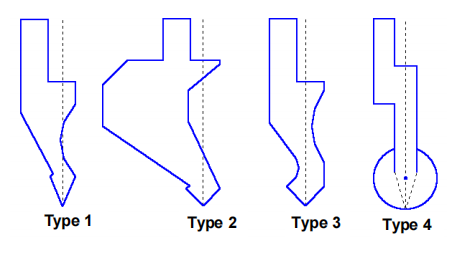
Using pre-set punches is recommended when the required punch is similar to standard catalog models, as it simplifies the setup process. For non-standard shapes, a full drawing is necessary to ensure accuracy.
ESA S650 Punches Setup for Custom Punch Drawing
Step 3: Entering Punch Dimensions
After selecting the punch type, the system will prompt you to enter key dimensions. These dimensions are critical because they directly affect bending calculations and anti-collision checks.
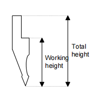
Enter the total height and working height as indicated in the figure.
Once the required data is entered, press “OK” to access the drawing page, where the punch geometry will be defined.
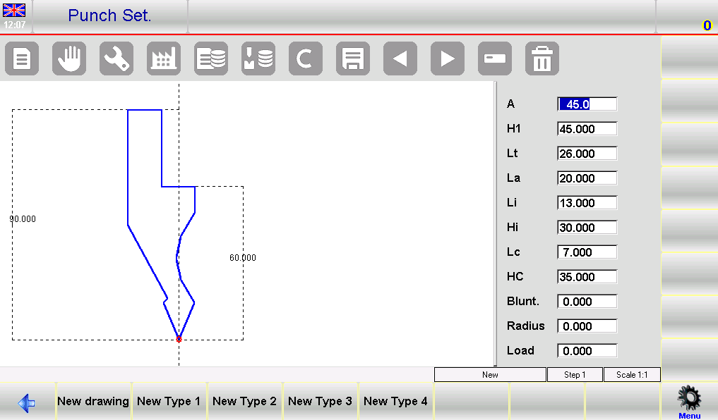
Step 4: Understanding the Drawing Interface
The drawing interface in the ESA S650 Punches Setup consists of:
- A left-side drawing window for visual representation
- Four data input panels on the right:
- Polar coordinates
- Cartesian coordinates
- Vertex data
- Arc data
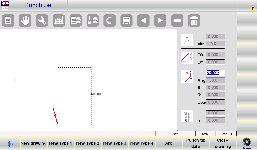
This structured interface allows operators to precisely define the punch shape using multiple input methods.
Step-by-Step Guide to Drawing Punches in ESA S650
Step 5: Defining the Punch Tip
The tip is the most critical part of the punch and must be defined first. Follow these steps:
- Enter tip length (lp)
- Input tip angle
- Define chamfer value (if applicable)
- Enter tip radius (R)
- Set maximum load capacity
After confirming these values, the system will automatically generate the initial geometry and prepare for the next segment.
Step 6: Completing the Punch Drawing
Continue building the punch shape by entering lengths and angles step by step:
- Input segment lengths (l1, l2, l3, etc.)
- Define angles between segments
- Use the arc function to create curved sections when needed
The drawing is created progressively, and higher accuracy in measurements leads to a more precise representation of the real punch.
Step 7: Using Graphic Assistance for Accuracy
If precise measurements are difficult to input, the system provides graphic assistance tools:
- Adjust angles by ±1°
- Adjust lengths by ±1 mm
These tools allow operators to visually match the drawing with the actual punch, improving setup accuracy.
Editing and Saving Punches in ESA S650 Punches Setup
Step 8: Correcting Drawing Data
During the drawing process, errors can be corrected by navigating between input fields. Operators can modify lengths and angles at any stage, ensuring the final design matches the real tool.
This flexibility is essential for achieving precise punch geometry and avoiding setup issues later.
Step 9: Saving the Punch Drawing
Once the drawing is complete:
- Save the punch to the system’s internal memory
- Enter a name using letters and numbers (e.g., catalog codes)
- Confirm by pressing “OK”
Saving ensures the punch can be reused in future programs, improving efficiency.
Using Pre-Set Punches in ESA S650 Punches Setup
Step 10: Modifying Pre-Set Punch Parameters
Pre-set punches come with predefined shapes and parameters. Operators can adjust these values to match actual tooling requirements. Once modified, the system automatically updates the drawing.
Step 11: When to Use Pre-Set Punches
Pre-set punches are ideal when:
- The tool matches standard catalog designs
- Quick setup is required
- Full custom drawing is unnecessary
They significantly reduce setup time while maintaining sufficient accuracy for most applications.
Key Tips for Efficient ESA S650 Punches Setup
Ensuring Accurate Tool Representation
Accurate punch data is essential because it affects both bending depth calculations and collision detection. Always verify dimensions before saving the drawing.
Avoiding Common Setup Mistakes
To ensure a smooth ESA S650 Punches Setup, follow these best practices:
- Use pre-set punches whenever possible
- Double-check all entered dimensions
- Utilize graphic assistance for fine adjustments
- Save correctly labeled punch data for future use
By following these steps, operators can achieve efficient setup, reduce errors, and maintain consistent bending quality.
Frequently Asked Questions(FAQ)
Should I use pre-set punches or create a new drawing?
It is recommended to use pre-set punches if the tool matches standard catalog shapes, as this saves time and simplifies setup. However, if the punch has a unique design, creating a full custom drawing in the ESA S650 Punches Setup is necessary for accuracy.
What should I do if I enter incorrect drawing data?
During the ESA S650 Punches Setup, you can easily correct errors by navigating between input fields and modifying lengths or angles. The system allows flexible editing before saving the final drawing.
How can I improve accuracy when drawing punches?
You can use the built-in graphic assistance tools to adjust angles by ±1° and lengths by ±1 mm. This helps visually match the drawing with the actual punch, ensuring better accuracy.
Conclusion
Proper ESA S650 Punches Setup is essential for ensuring accurate bending results and safe machine operation. By following the correct steps—selecting the right punch type, entering precise dimensions, completing accurate drawings, and saving the data properly—operators can significantly improve efficiency and reduce setup errors.
Using pre-set punches for standard tools and applying graphic assistance for fine adjustments can further simplify the process while maintaining high precision. Consistent and correct punch setup also supports reliable anti-collision checks and stable production performance.
For better results, always verify punch data before use and maintain an organized tool library for future programs. If you need further technical support, detailed documentation, or professional guidance, feel free to contact HARSLE or explore more resources on our website to optimize your press brake operations.


