


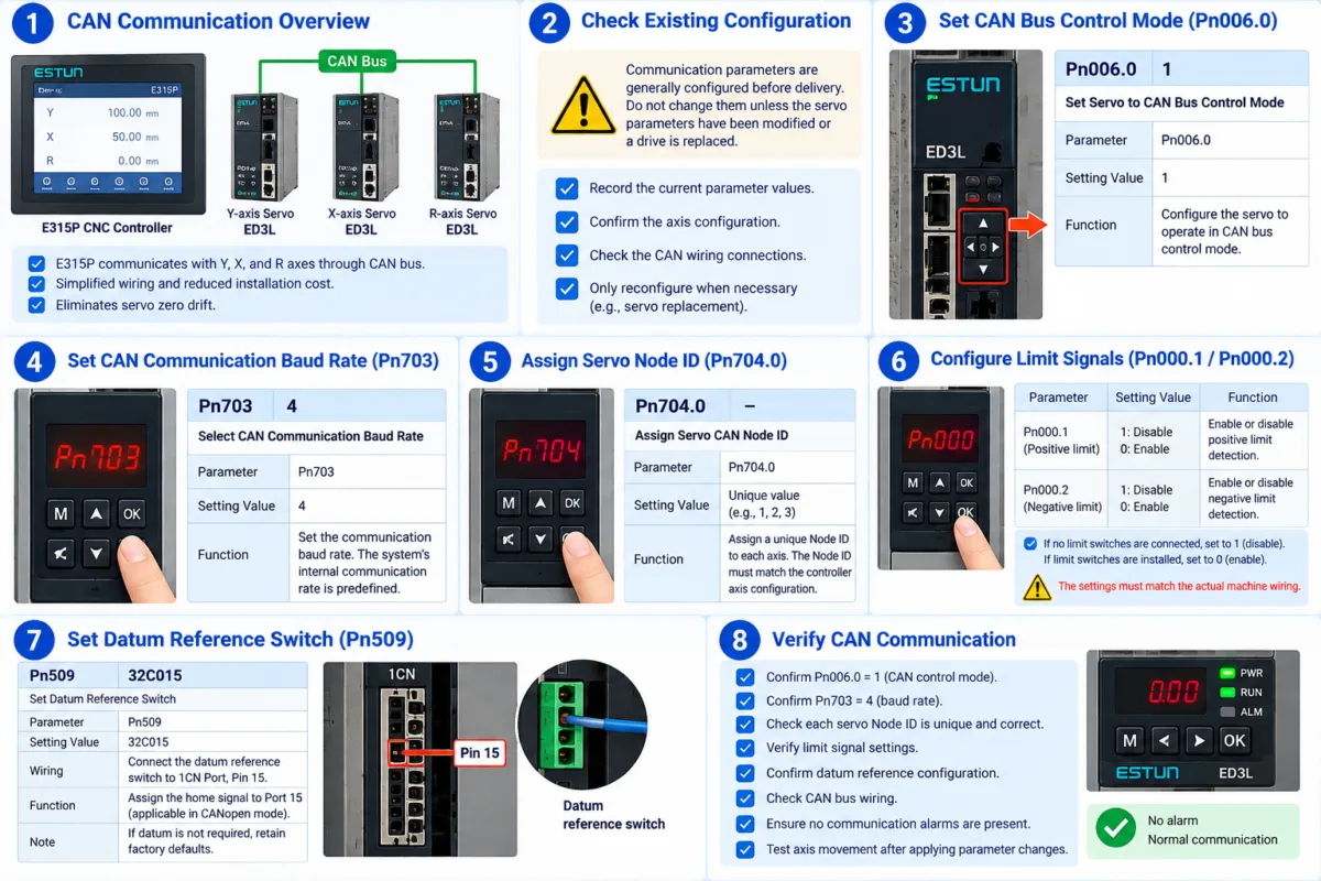
ESTUN E315P CAN Communication enables the CNC controller to communicate with servo drives through a CAN bus network. This communication method supports coordinated control of the X, Y, and R axes during press brake operation.
According to the E315P manual, CAN communication simplifies wiring, reduces installation costs, and eliminates servo zero drift.
When ED3L servo drives are used, several parameters must be configured correctly. This guide explains the essential settings, including communication mode, baud rate, node identification, limit switches, and datum reference configuration.
What Is ESTUN E315P CAN Communication?
ESTUN E315P CAN Communication uses a Controller Area Network (CAN) to exchange control information between the CNC controller and connected servo drives.
Each servo drive communicates through the shared network using its assigned Node ID.
The E315P manual specifies that ED3L servo drives support all axes in the system.
Communication parameters are normally configured before delivery. Users generally do not need to modify them unless servo parameters have been changed or a drive requires reconfiguration.
Before making adjustments, record the existing settings and verify the machine’s electrical configuration.
Step 1: Configure the CAN Control Mode
The first essential setting is the servo control mode.
| Parameter | Value | Function |
|---|---|---|
| Pn006.0 | 1 | Enable CAN Bus Control Mode |
Set Pn006.0 = 1 to configure the ED3L servo for CAN bus control.
This allows the servo drive to receive commands through the communication network.
If communication fails, the servo may display Alarm A.66.
The manual also lists Pn001 for restoring factory defaults. However, a factory reset should only be performed when necessary because it may erase existing machine-specific settings.
Step 2: Set the CAN Communication Baud Rate
The baud rate determines the communication speed between the controller and servo drives.
For ED3L configuration, the manual specifies:
| Parameter | Value |
|---|---|
| Pn703 | 4 |
Set Pn703 = 4.
The E315P uses a predefined internal communication rate, so the servo configuration must match the controller’s requirements.
Incorrect baud rate settings may prevent successful communication.
When checking ESTUN E315P CAN Communication, confirm this parameter before changing other servo settings.
Step 3: Assign the Servo Node ID
Each servo drive requires a unique CAN Node ID.
The corresponding parameter is:
Pn704.0 — Servo CAN Node ID
The Node ID must match the axis assignment configured in the E315P Machine Parameters.
For example:
Controller Axis Node ID = 1 → Servo Node ID = 1
When configuring multiple servo drives, confirm that:
- Each servo has a unique Node ID.
- The Node ID corresponds to the correct machine axis.
- Controller and servo settings are consistent.
Incorrect or duplicated addresses can cause communication problems or prevent the controller from identifying the intended axis.
Step 4: Configure Limit Switch Signals
The ED3L servo provides separate settings for positive and negative limit detection.
| Parameter | No Limit Switch | Limit Switch Connected |
|---|---|---|
| Pn000.1 | 1 — Disable | 0 — Enable |
| Pn000.2 | 1 — Disable | 0 — Enable |
Pn000.1 controls positive limit detection, while Pn000.2 controls negative limit detection.
These settings must match the actual machine wiring.
If physical limit switches are installed, the corresponding detection functions should remain enabled.
Do not disable an installed limit switch merely to clear an alarm. Check the wiring and safety conditions before modifying these parameters.
Step 5: Configure the Datum Reference Switch
The E315P manual identifies the following ED3L parameter:
| Parameter | Value |
|---|---|
| Pn509 | 32C015 |
This parameter is associated with the datum reference switch.
For the specified configuration, connect the reference switch to 1CN Port, Pin 15 on the servo drive.
The home signal is assigned to Port 15 in the applicable CANopen configuration.
If datum referencing is not required, retain the factory settings.
Correct datum configuration helps ensure that the servo system recognizes the intended reference signal.
Step 6: Verify ESTUN E315P CAN Communication
After completing the configuration, verify the essential parameters.
| Inspection Item | Required Setting |
|---|---|
| CAN Control Mode | Pn006.0 = 1 |
| Communication Baud Rate | Pn703 = 4 |
| Servo Node ID | Unique and matching controller |
| Positive/Negative Limits | Match actual wiring |
| Datum Reference | Match the required configuration |
Check the CAN communication connections against the electrical diagram.
Confirm that the controller recognizes the connected servo drives and that no communication alarms are present.
Follow the servo manufacturer’s instructions for applying parameter changes before testing axis movement.
How to Troubleshoot CAN Communication Problems
If ESTUN E315P CAN Communication fails, inspect the configuration systematically.
First, confirm that the servo is operating in CAN bus control mode.
Next, check the baud rate and verify that each servo Node ID matches the corresponding controller axis.
If Alarm A.66 appears, inspect the communication wiring and parameter consistency.
Avoid changing unrelated servo parameters until the communication settings have been verified.
Key Considerations for Reliable Communication
Reliable ESTUN E315P CAN Communication depends on correct configuration of the ED3L servo drives and consistent settings between the controller and connected axes.
The most important parameters are Pn006.0, Pn703, and Pn704.0. Limit detection and datum reference settings must also correspond to the actual machine configuration.
Since these parameters are generally configured at the factory, unnecessary modifications should be avoided. When replacing a servo drive or restoring parameters, follow the manual’s configuration requirements and verify communication before resuming normal machine operation.
Frequently Asked Questions(FAQ)
Can Multiple Servo Drives Use the Same CAN Node ID?
No. Each servo drive must have a unique Node ID on the CAN network. Duplicate addresses may cause communication conflicts and prevent the controller from identifying the correct servo axis.
Why Is the Servo Not Recognized After Replacement?
A replacement servo may have different communication settings from the original drive. During ESTUN E315P CAN Communication troubleshooting, verify the CAN control mode, baud rate, and Node ID. Also confirm that the replacement drive is compatible with the machine’s existing configuration.
Does Every ED3L Servo Require Datum Reference Configuration?
Not necessarily. The datum reference setting depends on the machine’s axis configuration. If the corresponding datum function is not required, the manual instructs users to retain the factory defaults.
Conclusion
Correct ESTUN E315P CAN Communication ensures reliable data exchange between the CNC controller and ED3L servo drives.
The main configuration parameters include Pn006.0 for CAN control mode, Pn703 for communication baud rate, and Pn704.0 for servo Node ID assignment. Limit switch detection and datum reference settings must also match the actual machine wiring.
Since these parameters are normally configured at the factory, unnecessary modifications should be avoided. When replacing servo drives or restoring settings, technicians should verify parameter consistency, inspect communication connections, and confirm normal operation before enabling axis movement.
Following these procedures helps maintain stable ESTUN E315P CAN Communication and reduces configuration-related problems during press brake operation.


