


Correct ESTUN E315P Servo Axis configuration is essential for accurate and reliable press brake movement. The E315P controller manages several machine axes, including the X-axis for backgauge front and rear movement, the R-axis for backgauge vertical movement, and the Y-axis for ram movement. These axes use servo control and must be configured according to the mechanical structure and movement direction of the machine.
Before setting detailed servo parameters, technicians should understand the axis definitions, origin positions, and directionality specified by the E315P system. This guide explains the basic ESTUN E315P Servo Axis configuration process and the key principles that should be confirmed before entering individual axis parameters.
What Axes Does the ESTUN E315P Control?
An axis represents a fundamental direction along which a machine component performs linear or rotational movement. The E315P uses different axes to coordinate the main movements required during bending.
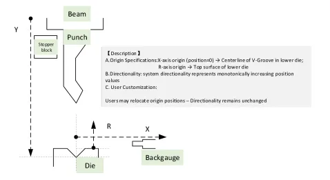
The controller can manage the following machine movements:
- X-axis: Controls the front and rear movement of the backgauge.
- R-axis: Controls the upward and downward movement of the backgauge.
- Y-axis: Controls the upward and downward movement of the ram.
- C-axis: Controls lower-table deflection compensation.
These axes do not all use the same control method. Understanding their classification is important before configuring the controller.
What Is an ESTUN E315P Servo Axis?
The X, Y, and R axes are classified as servo axes and are driven by servo motors. These motors provide controlled movement according to the position commands generated by the E315P.
The C-axis is different. It is classified as an auxiliary axis and can use hydraulic or mechanical actuation for deflection compensation.
Therefore, when configuring an ESTUN E315P Servo Axis, the main focus is on X, Y, and R rather than the C-axis.
Although these servo axes control different machine components, the manual indicates that the X, Y, and R axes use the same basic parameter structure. The X-axis is therefore used as the primary example when explaining servo-axis parameters.
How to Access ESTUN E315P Servo Axis Parameters?
Servo-axis parameters are available through the controller’s parameter interface.
Obtain Level 1 Permission
Before changing machine parameters, obtain Level 1 permission.
This access level is required because servo-axis settings directly affect machine movement. Incorrect parameter changes may cause the actual movement of an axis to differ from the intended controller command.
Enter the Parameters Interface
After obtaining the required permission, open the Parameters interface and select the target axis.
For example, selecting the Y-axis opens the corresponding Y-Axis Parameters interface shown in the manual.
The same general procedure can be used when accessing other servo-axis settings.
Before changing individual parameters, however, the movement direction and origin definition of each axis should be confirmed.
How Are Servo Axis Origins Defined?
The origin provides the reference point from which the controller determines an axis position. Correct origin definition is therefore an important part of ESTUN E315P Servo Axis configuration.
The manual provides specific origin definitions for the X-axis and R-axis.
X-Axis Origin
For the X-axis, the origin position is defined as 0 at the centerline of the V-groove in the lower die.
This establishes a mechanical reference for the front and rear positioning of the backgauge.
Because the X-axis determines the backgauge position used during bending, its position values must correspond correctly with this reference.
R-Axis Origin
For the R-axis, the origin position is defined as 0 at the top surface of the lower die.
The R-axis controls the vertical position of the backgauge, so this reference allows the controller to determine the backgauge height relative to the lower tooling.
These reference definitions are important when commissioning the machine or checking whether displayed axis positions correspond to actual mechanical positions.
How Is Servo Axis Direction Defined?
In addition to the origin, technicians must understand the directionality used by the controller.
For the ESTUN E315P Servo Axis, system directionality represents the direction in which the displayed position value increases monotonically.
In other words, the controller uses a defined positive direction for increasing axis position values.
This direction should not be confused with an arbitrary physical description such as left, right, forward, or backward without first checking the actual machine structure.
The motor direction, encoder feedback direction, and system axis direction must work consistently so that the controller receives the expected position feedback when an axis moves.
What Should Be Confirmed Before Servo Parameter Setup?
Before entering detailed servo parameters, the movement direction of the servo axis should be defined and verified.
The E315P manual specifically requires users to define axis movement directions before completing servo parameter setup.
Technicians should confirm:
- Which machine component the axis controls
- The mechanical origin of the axis
- The direction of increasing position values
- The required motor rotation direction
- The encoder counting direction
- The actual mechanical movement of the axis
These factors are related. If one is configured incorrectly, the controller’s displayed movement may not correspond with the actual movement of the machine.
Do X, Y, and R Axes Use Different Parameters?
The X, Y, and R axes perform different mechanical functions, but their servo parameter structures are essentially the same within the E315P.
The manual uses the X-axis as the example for explaining the detailed parameter configuration.
These parameters include items related to:
- Axis enable
- Servo type
- Motor direction
- Encoder counting method
- Datum configuration
- Servo ID
- Positioning characteristics
- Movement speed
- Software position limits
- Positioning tolerance
- Acceleration and deceleration
Because these settings contain many individual values and operating conditions, they should be configured according to the actual machine rather than copied directly from another press brake.
The detailed X-axis parameters can be examined separately after the basic ESTUN E315P Servo Axis principles are understood.
What Should You Check After Servo Axis Configuration?
After configuring the basic servo-axis settings, verify the relationship between the controller command, actual mechanical movement, and position feedback before normal machine operation.
Check whether the axis moves in the intended direction and whether the displayed position changes correctly.
The mechanical origin should also correspond with the reference defined for that axis.
If the actual movement direction and displayed position direction do not match, review the relevant motor and encoder settings before continuing.
During commissioning, checking these relationships carefully can help identify configuration problems before detailed positioning parameters are adjusted.
Frequently Asked Questions(FAQ)
Can I Copy Servo Axis Parameters From Another Machine?
It is not recommended. Even machines using the same E315P controller may have different mechanical structures, servo drives, transmission ratios, travel limits, and reference positions. Parameters should be verified against the actual machine configuration.
Why Does the Displayed Position Change Incorrectly?
Check whether the encoder counting direction corresponds with the actual mechanical movement. The position feedback should increase or decrease consistently with the defined system direction.
Conclusion
Correct ESTUN E315P Servo Axis configuration begins with understanding the relationship between the X, Y, and R axes, their mechanical origins, and their movement directions. The X-axis controls backgauge front and rear movement, the R-axis controls vertical backgauge movement, and the Y-axis controls ram movement.
Before adjusting detailed servo parameters, technicians should verify the axis origin, system directionality, motor rotation, and encoder feedback. Although the X, Y, and R axes use similar parameter structures, their actual settings must match the specific machine configuration.
Once these basic ESTUN E315P Servo Axis principles are confirmed, technicians can proceed to detailed parameters such as servo type, datum settings, positioning speed, software limits, tolerance, and acceleration/deceleration settings.


