


The ESTUN E315P X-Correction is a programming parameter associated with internal and external dimension selection during press brake workstep programming. Understanding this function helps operators select the appropriate dimensional reference when preparing bending programs.
According to the ESTUN E315P operating manual, X-Correction can be enabled or disabled through the controller’s programming constants. However, this function should not be confused with mechanical backgauge calibration or automatic correction of X-axis positioning errors.
This guide explains the purpose of X-Correction, its available settings, the difference between internal and external dimensions, and how operators can verify their programming configuration.
What Is ESTUN E315P X-Correction?
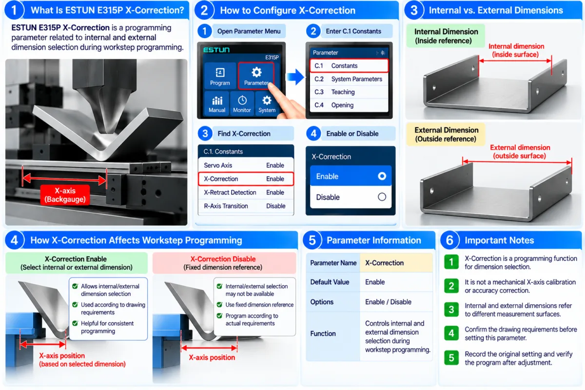
The ESTUN E315P X-Correction is a configurable parameter found in the controller’s C.1 Constants section.
It is associated with the selection of internal and external dimensions during bending workstep programming.
The operating manual provides the following parameter information:
| Parameter | Specification |
|---|---|
| Parameter Name | X-Correction |
| Default Value | Enable |
| Available Options | Enable / Disable |
| Function | Controls internal and external dimension selection during workstep programming |
The default setting is Enable.
Unlike an axis calibration parameter, X-Correction relates to the dimensional reference used when preparing bending operations.
The manual does not provide a detailed correction formula or specify an automatic mechanical compensation procedure for this parameter.
Therefore, operators should understand its programming purpose before making adjustments.
How Does X-Correction Affect Workstep Programming?
The ESTUN E315P X-Correction is relevant when operators define dimensions for individual bending worksteps.
In sheet metal fabrication, dimensions may be specified using different reference surfaces depending on the drawing and bending requirements.
For example, a finished component may have dimensions measured along its internal surfaces or external surfaces.
These measurements are not necessarily identical because the sheet metal has a physical thickness and the finished bend has a specific geometry.
When preparing a bending program, operators should identify which dimensional reference corresponds to the engineering drawing.
Internal Dimension Reference
An internal dimension generally refers to a measurement based on the inside surfaces of a formed sheet metal component.
This reference may be used when the drawing specifies internal clearances or dimensions between inside faces.
External Dimension Reference
An external dimension generally refers to a measurement based on the outside surfaces of the formed component.
This reference may be used when the drawing specifies overall external dimensions.
The ESTUN E315P X-Correction parameter is associated with selecting between these dimensional references during programming.
However, the exact relationship between this setting and the controller’s numerical calculations should be verified against the applicable controller software and machine configuration.
How to Configure ESTUN E315P X-Correction
Before changing the parameter, confirm that the intended bending program and dimensional requirements are understood.
Step 1: Access the Constants Menu
Open the E315P controller’s parameter settings.
Locate the C.1 Constants section described in the operating manual.
Find the parameter labeled X-Correction.
Step 2: Check the Current Setting
Review whether the parameter is currently set to Enable or Disable.
According to the manual, Enable is the default value.
If the machine has already been commissioned and operates normally, record the existing configuration before making changes.
Step 3: Select Enable or Disable
Choose the required setting according to the programming requirements.
Enable: Activates the X-Correction option associated with internal and external dimension selection.
Disable: Disables this option.
The manual identifies these two choices but does not provide sufficient detail to establish every resulting calculation or interface behavior.
For this reason, operators should avoid assuming that changing the parameter automatically recalibrates the backgauge.
Step 4: Verify the Programming Configuration
After changing the ESTUN E315P X-Correction, review the relevant bending workstep.
Confirm that the intended dimensional reference is available and correctly selected.
Check the programmed X-axis values against the engineering drawing and the required bending dimensions.
Before production, verify the machine’s positioning behavior under appropriate safe operating conditions.
Internal vs. External Dimensions in Press Brake Programming
Understanding the difference between internal and external dimensions is essential when using dimensional references in bending programs.
Consider a simple sheet metal component with a 90-degree bend.
The internal dimension is measured using the inside surfaces of the formed part, while the external dimension is measured using its outside surfaces.
Because the material has thickness, these measurements may differ.
The relationship also depends on the component geometry and the specific measurement points.
For this reason, operators should not assume that converting between internal and external dimensions always involves adding or subtracting one sheet thickness.
The correct interpretation depends on the engineering drawing and bending geometry.
When using the ESTUN E315P X-Correction, the dimensional reference should be consistent with the drawing requirements.
Incorrect interpretation of the reference may lead to unsuitable programmed dimensions even when the machine’s mechanical positioning system operates normally.
Is X-Correction the Same as X-Axis Calibration?
No. These functions should be distinguished.
X-axis calibration concerns the relationship between the actual backgauge position and the position recognized by the controller.
It may involve reference positioning, axis teaching, or other machine-specific commissioning procedures.
By comparison, the ESTUN E315P X-Correction parameter is associated with internal and external dimension selection during workstep programming.
Changing this parameter should not be treated as a substitute for correcting mechanical alignment, reference-position errors, or servo positioning faults.
If the backgauge does not reach its commanded position, operators should investigate the relevant axis settings and mechanical conditions rather than relying on X-Correction alone.
Common X-Correction Setting Mistakes
Confusing Dimensional References
Internal and external dimensions refer to different measurement surfaces.
Operators should confirm the intended reference before entering bending dimensions.
Assuming X-Correction Repairs Positioning Errors
The parameter is not documented as a general-purpose mechanical accuracy correction.
Unexpected backgauge positioning should be investigated separately.
Changing Settings Without Recording the Original Value
The default setting is Enable, but an existing machine may have been configured for specific operating requirements.
Record the current setting before making changes.
Ignoring Workstep Verification
After adjusting the ESTUN E315P X-Correction, operators should review the programmed dimensions and confirm that the intended reference is being used.
A configuration change should not be accepted without checking its effect on the relevant program.
Practical Recommendations for X-Correction Configuration
When configuring the ESTUN E315P X-Correction, begin by reviewing the engineering drawing and identifying whether internal or external dimensions are required.
Check the existing controller setting and avoid changing parameters that are unrelated to the dimensional reference.
If a configuration change is necessary, verify the programmed X-axis values and perform an appropriate positioning check before production.
For machines already operating correctly, unnecessary changes to established settings should be avoided.
The ESTUN E315P X-Correction should be understood as a workstep programming function rather than a universal solution for backgauge accuracy problems.
By selecting the appropriate dimensional reference and verifying the resulting program, operators can reduce programming misunderstandings and maintain more consistent press brake operations.
Frequently Asked Questions(FAQ)
Does X-Correction Automatically Correct Bending Angle Errors?
No. The ESTUN E315P X-Correction is associated with internal and external dimension selection during workstep programming. It is not documented as a bending angle compensation function. Angle deviations should be investigated through the relevant bending parameters, tooling information, material properties, and machine calibration.
Can X-Correction Be Used to Compensate for Material Thickness?
Internal and external dimensions can differ because of material thickness and bending geometry. However, the manual does not specify a universal thickness compensation formula for the ESTUN E315P X-Correction. Operators should use the correct dimensional reference and verify the resulting program rather than assuming a fixed compensation value.
Why Are the Programmed Dimensions Different from the Engineering Drawing?
A difference may result from using an incorrect dimensional reference, misunderstanding the drawing, or entering unsuitable workstep values. Operators should confirm whether the drawing specifies internal or external dimensions and review the relevant programming settings before investigating mechanical positioning problems.
Conclusion
The ESTUN E315P X-Correction is a programming parameter associated with internal and external dimension selection during press brake workstep programming. According to the E315P operating manual, its default setting is Enable, with Enable and Disable available as configuration options.
Understanding the difference between internal and external dimensions is essential for interpreting engineering drawings and preparing bending programs. However, X-Correction should not be confused with mechanical backgauge calibration, X-axis teaching, or bending angle compensation.
Before changing the parameter, operators should record the existing configuration, confirm the required dimensional reference, and verify the programmed X-axis values.
By configuring the ESTUN E315P X-Correction appropriately and checking the resulting workstep settings, operators can reduce dimensional programming errors and support more consistent press brake operations.


